Direct Current Brushless Machine and Wind Turbine System

a brushless machine and wind turbine technology, applied in the direction of machines/engines, liquid fuel engines, electric generator control, etc., can solve the problems of inefficient idle rate, high capital investment of remote power installations, and serious reliability and intermittent generation nature of wind power

Inactive Publication Date: 2010-06-17
GEDDRY MARY +1
View PDF66 Cites 63 Cited by
  • Summary
  • Abstract
  • Description
  • Claims
  • Application Information

AI Technical Summary

Benefits of technology

[0006]It is an object of this invention to provide an improved brushless direct current machine for multiple appl

Problems solved by technology

These remote power installations are initially very capital intensive: utility substation systems and long range transmission lines must be added to the installations delivering electrical power to the end consumer.
As the percentage of power produced by big wind turbines becomes a larger percentage of total produced electrical power, the reliability and intermittent generating nature of wind power becomes a serious problem.
In Scandinavia, Europe, Texas, and elsewhere, the intermittent nature of wind power requires the c

Method used


Image

  • Direct Current Brushless Machine and Wind Turbine System
  • Direct Current Brushless Machine and Wind Turbine System
  • Direct Current Brushless Machine and Wind Turbine System

Examples


Embodiment Construction

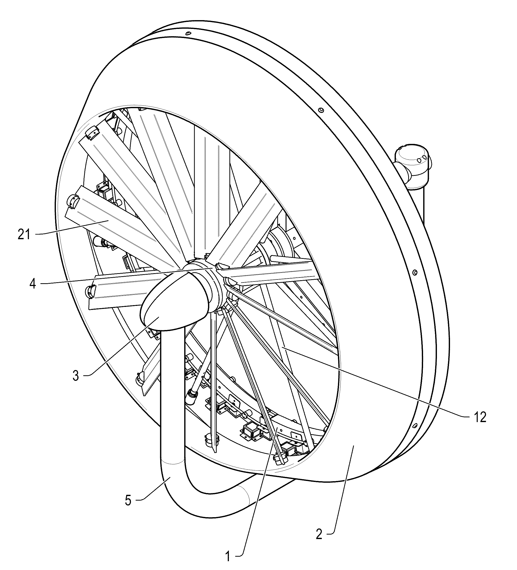
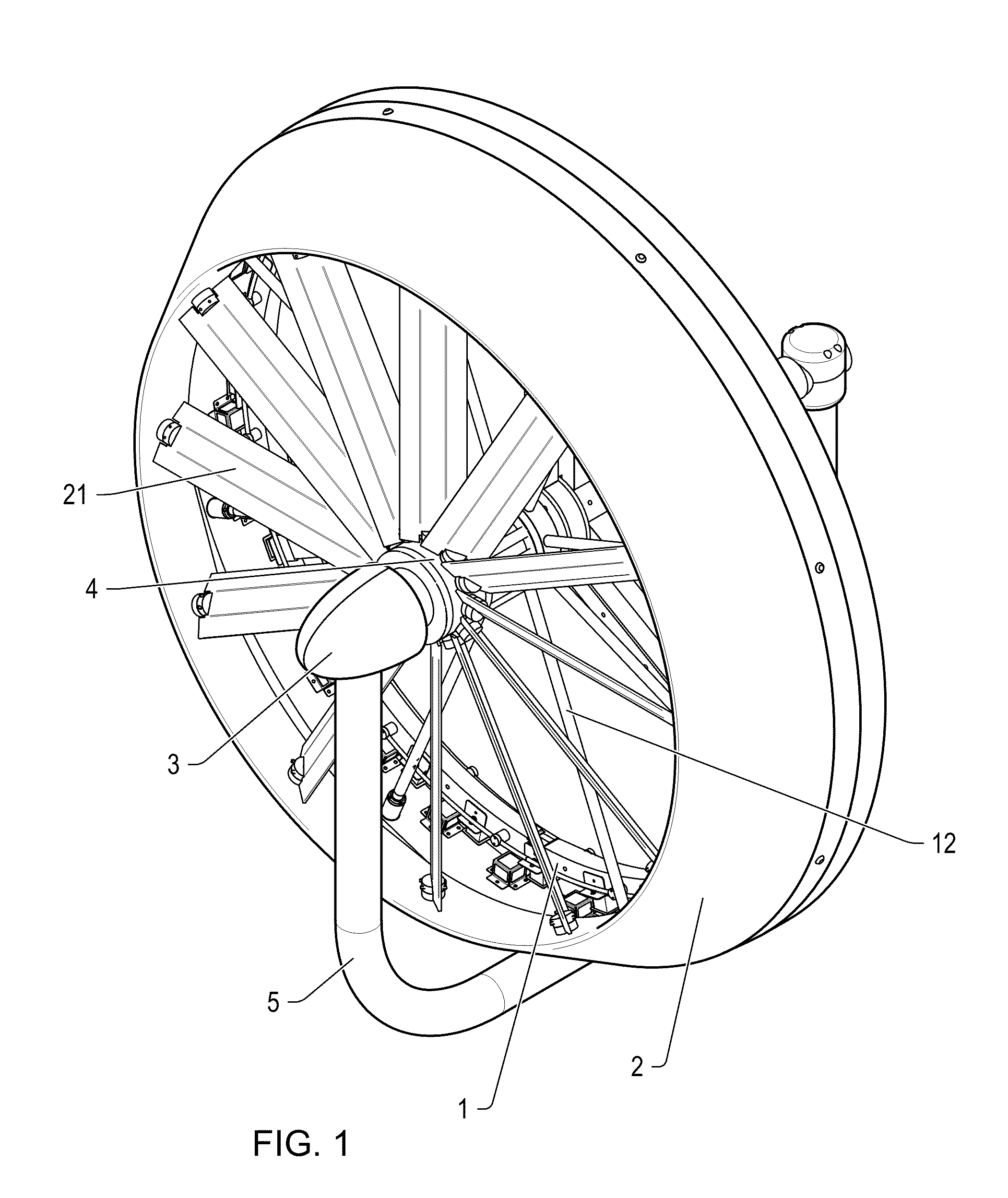
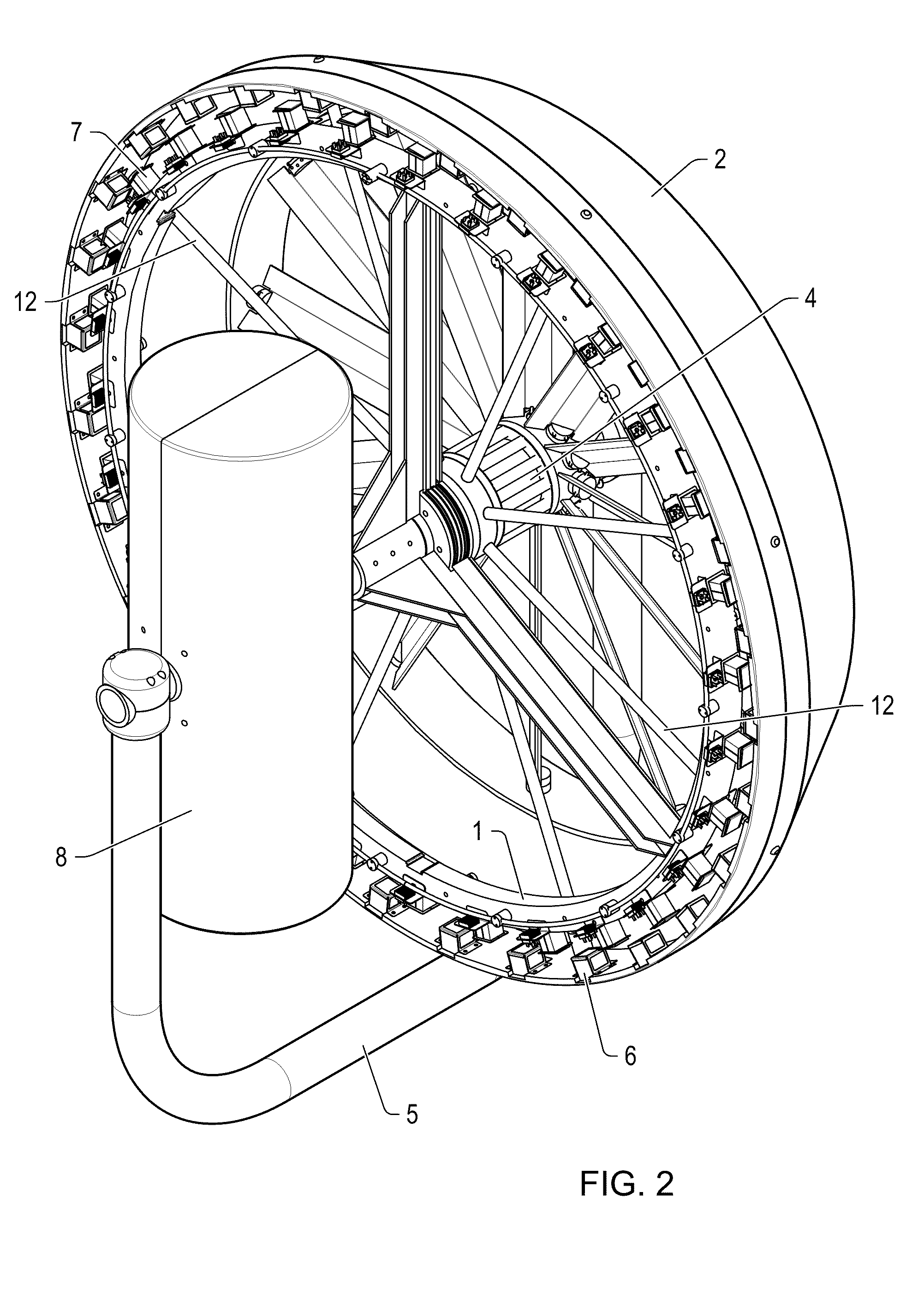
[0022]A preferred embodiment of a wind turbine in accordance with the present invention comprises a ducted wind turbine having the rotor and stator positioned near at end of the fan blades away from the axis of rotation.

[0023]Ducted wind turbines include a structure near the turbine that affects the wind flow through the turbine blades. Wind turbines of all sizes have long been built with associated structures and housings that provide aerodynamic features which affect the air flow through the turbine. The Persians, several thousand years ago, at the time of the attempted Greek conquests, were building various cooling towers, and small open fan type turbines, which were placed within sided structures, open in the direction of incoming and exiting wind flow. Some early 20th Century machines also featured housings and blade tip confinement schemes for legitimate reduction of power limiting blade tip vortices generated at radial right angles to the axial air flow.

[0024]A study funded b...


PUM


Abstract

A direct current brushless electric machine is described that comprises a sequence of permanent magnets where the N and S magnetic poles being alternately arranged adjacent to each other, each exerting a magnetic field; phase coils are composed of a group of conductors, each conductor being laid essentially in parallel with each other, each coil being displaced by a full range of a single magnetic pole of the permanent magnet, such that each phase coil is alternately disposed adjacent to each other; and magnetic field or every other coil is in the same orientation to form an armature positioned opposite to the permanent magnet movable with respect to the armature with a predetermined amount of air gap provided between the phase coils and the permanent magnets. The electric machine operates as a generator when the power is flowing from a prime mover, such as the turbine blade extracting energy from the wind or water. The electric machine operates as a motor when the current is applied to the coils in a sequence to move the rotor when the turbine blades move the wind or water.
Also described is an aerodynamic system comprising inner and outer annulus disposed driving fans, with a pressure differential flow enhancing aerodynamic housing, able to concentrate and make laminar rough and turbulent intake air molecule flows, creating a smooth rotationally organized downstream vortex field, with maximum power extraction from building structure directed velocity flow enhancements.

Description

[0001]The application is a continuation-in-part of U.S. patent application Ser. No. 12 / 472,114, filed May 26, 2009, which is a continuation of U.S. patent application Ser. No. 12 / 264,226, filed Nov. 13, 2008, which claims priority from U.S. Prov. Pat. App. No. 60 / 984,965, filed Nov. 2, 2007.FIELD OF THE INVENTION[0002]The present invention is related to electric generators and motors, and in particular to a generator useful for generating electricity from the wind.BACKGROUND OF THE INVENTION[0003]Wind is presently the fastest growing renewable energy source, averaging annual growth rates of 29% worldwide for the last decade. Most money and public interest invested in wind turbine projects generally has been invested in large wind farms with multi megawatt generating capability, even though such installations normally occur in remote locations far from the electric power consuming market. These remote power installations are initially very capital intensive: utility substation system...

Claims


Application Information

Patent Timeline
IPC IPC(8): F03D9/00H02K21/12F03D1/04
CPCF03B17/061H02K2213/12F03D9/002F04D25/0606F05B2220/7066F05B2240/33H02K16/00H02K21/225H02K41/03Y02B10/30Y02B10/70Y02E10/28Y02E10/725H02K7/1869F03D1/00F03D9/25Y02E10/20Y02E10/72F03D1/04
Inventor GEDDRY, MARYSHEBLE, GERALD
Owner GEDDRY MARY
Why Eureka
Try Eureka