Flexible optical waveguide, process for its production, and epoxy resin composition for flexible optical waveguides
- Summary
- Abstract
- Description
- Claims
- Application Information
AI Technical Summary
Benefits of technology
Problems solved by technology
Method used
Image
Examples
example 1
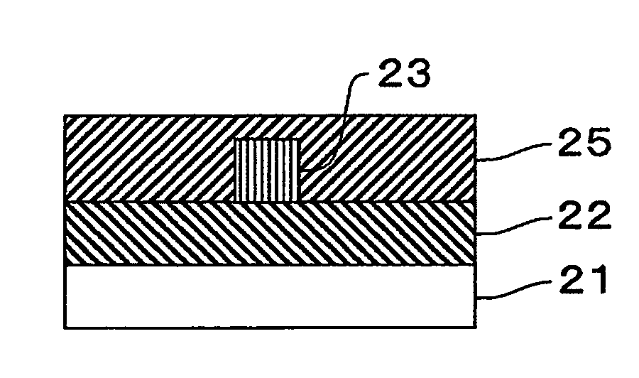
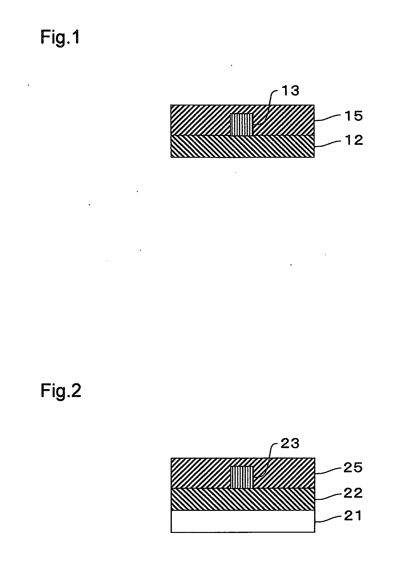
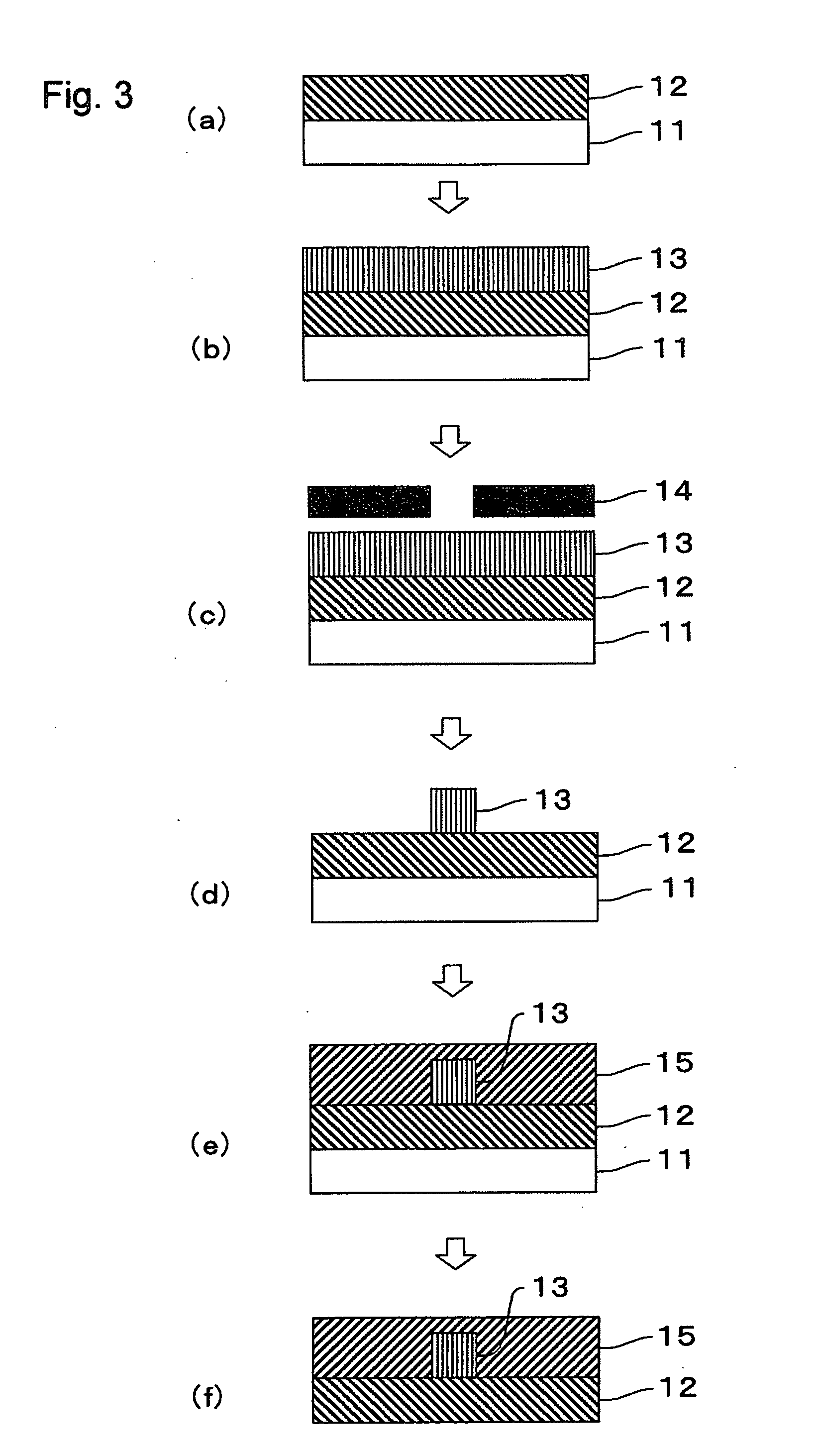
[0207]First, the epoxy resin composition (1) for cladding layers was spin coated on a silicon substrate, and ultraviolet irradiation was carried out at an illumination intensity of 10 mW / cm2 for 15 minutes, i.e., at an exposure energy of 9 J / cm2, using an exposure apparatus (product name: MA-60F, available from Mikasa Co., Ltd.) with a high pressure mercury lamp as a light source (having a wavelength of 365 nm) to form a lower cladding layer composed of an epoxy film having a thickness of 50 μm. The refractive index of the lower cladding layer was measured at a wavelength of 830 nm using a prism coupler (product name: SPA-4000, available from SAIRON TECHNOLOGY, INC.) and found to be 1.53.
[0208]The epoxy resin composition (1) for core layers was spin coated on the resultant lower cladding layer, and ultraviolet irradiation was carried out through a photomask at an illumination intensity of 10 mW / cm2 for 15 minutes, i.e., at an exposure energy of 9 J / cm2, using an exposure apparatus (...
example 2
[0212]A flexible optical waveguide (2) having a lower cladding layer, a core layer, and an upper cladding layer, all of which were composed of epoxy films, was obtained in the same manner as described in Example 1, except that the epoxy resin composition (2) for cladding layers was used in place of the epoxy resin composition (1) for cladding layers at the time of forming the upper cladding layer.
[0213]When the waveguide loss of the resultant flexible optical waveguide (2) was measured without being bent, it was 0.13 dB / cm. Further, using the resultant flexible optical waveguide (2), the waveguide loss at the time of being bent at 90 degrees with a radius of 10 mm was measured according to the test method of polymer waveguides (7.1.1 Bending Test JPCA-PE02-05-01S) published by Japan Printed Circuit Association and found to be the same as the waveguide loss measured without being bent, and no increase of waveguide loss was observed. Further, when waveguide loss was measured in a stat...
example 3
[0214]A flexible optical waveguide (3) having a lower cladding layer, a core layer, and an upper cladding layer, all of which were composed of epoxy films, was obtained in the same manner as described in Example 1, except that the epoxy resin composition (2) for cladding layers was used in place of the epoxy resin composition (1) for cladding layers at the time of forming the lower cladding layer.
[0215]When the waveguide loss of the resultant flexible optical waveguide (3) was measured without being bent, it was 0.13 dB / cm. Further, using the resultant flexible optical waveguide (3), the waveguide loss at the time of being bent at 90 degrees with a radius of 10 mm was measured according to the test method of polymer waveguides (7.1.1 Bending Test JPCA-PE02-05-01S) published by Japan Printed Circuit Association and found to be the same as the waveguide loss measured without being bent, and no increase of waveguide loss was observed. Further, when waveguide loss was measured in a stat...
PUM
| Property | Measurement | Unit |
|---|---|---|
| Temperature | aaaaa | aaaaa |
| Flexibility | aaaaa | aaaaa |
| Refractive index | aaaaa | aaaaa |
Abstract
Description
Claims
Application Information
 - R&D
- Intellectual Property
- Life Sciences
- Materials
- Tech Scout
- Unparalleled Data Quality
- Higher Quality Content
- 60% Fewer Hallucinations
Browse by: Latest US Patents, China's latest patents, Technical Efficacy Thesaurus, Application Domain, Technology Topic, Popular Technical Reports.
© 2025 PatSnap. All rights reserved.Legal|Privacy policy|Modern Slavery Act Transparency Statement|Sitemap|About US| Contact US: help@patsnap.com


