
Apparatus and method for non-invasive and minimally-invasive sensing of parameters relating to blood

a technology of parameters and apparatus, applied in the field of vital bodily function monitoring techniques, can solve the problems of inconvenient use, large care, and no longer relevant sources of errors, and achieve the effect of reducing the number of sources of errors and avoiding the use of unnecessary equipmen

Inactive Publication Date: 2010-06-17
SKYLINE BIOMEDICAL
View PDF6 Cites 20 Cited by
  • Summary
  • Abstract
  • Description
  • Claims
  • Application Information

AI Technical Summary

Benefits of technology

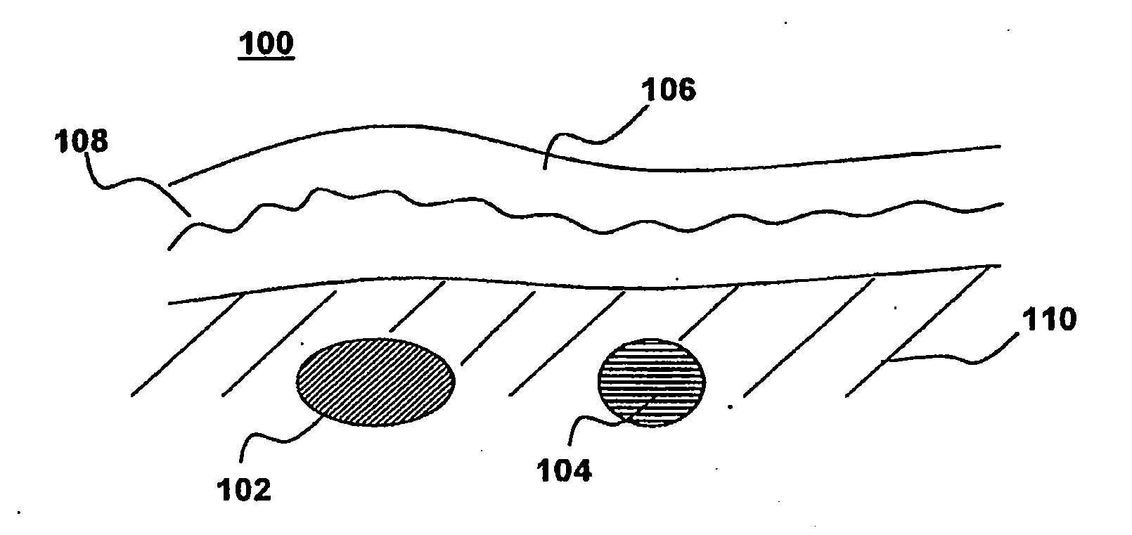
[0021]There is a need in the art to be able to measure venous oxygen saturation levels in various vascular structures in the body, and from this be able to calculate cardiac output. There is a need to make these measurements non-invasively or with minimal invasiveness. There is a need to be able to make these measurements in an MRI- / CT / X-Ray instrument compatible manner, thus preferably not using ferromagnetic materials in construction, and using designs such that the probe on / in the body may be remotely coupled to the control system away from the magnetic field or ionizing radiation sources generated by the MRI instrument or CT / X-Ray. There is a need in the art to make these measurements in a manner that does not depend on the melanin content of the skin. There is a need to make these measurements in a manner such that the result may be arrived at in a short time period, i.e. such that extensive post-processing of the data is not required, so that the physician may make accurate timely diagnostic and therapeutic decisions. Many or all of the disadvantages associated with the prior art can be significantly alleviated through embodiments of the present invention.
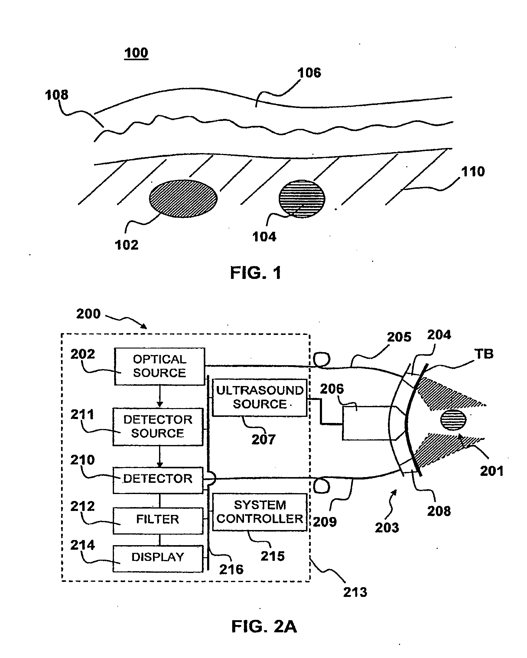
[0024]An ultrasound transducer can also be used in combination with the optical methods to generate an image of tissues within the first area including the target structure to enable placement of the one or more optical transmitters and the one more optical receivers on the patient so as to enhance the accuracy of the monitoring of the system. The ultrasound transducer can also be configured to provide an ultrasound radiation pressure field to modulate the target structure at a modulation frequency. The ultrasound pressure modulation can be preformed continuously, or it can be operated temporarily, in order to calculate a calibration adjustment to the optical measurement.

Problems solved by technology

Many new methods have attempted to replace the thermodilution technique, but none have so far gained acceptance.
It is generally considered the most accurate method currently available, although there are many possibilities of introducing errors, and considerable care is needed.
However when using the Fick method to trend cardiac output over a short time interval, i.e. during an operation or in an intensive care unit stay, many of these sources of errors are no longer pertinent.
Studies have been reported with mostly poor results, but in exceptional cases good correlations compared to a reference method.
The accuracy of this technique is increased when the electrodes are placed directly in the left ventricle, rather than on the chest, however this also increases its invasiveness.
However, in clinical settings, the lower precision of the continuous cardiac output techniques may be outweighed by their advantages of being automatic and continuous.
Unfortunately, measurements from such oxygen monitors cannot be reliably correlated to oxygenation in the patient's venous blood.
Imaging the speckle resulting from trajectory changes requires significant computation power and post-processing to yield an image.
The technique has limited resolution, and is not yet capable of yielding functional (oxygenation) information in a fast flowing vessel.
In addition, the frequency shift can be to both larger and smaller frequency of the initial carrier wave, and therefore some self-cancellation may result.

Method used


Image

  • Apparatus and method for non-invasive and minimally-invasive sensing of parameters relating to blood
  • Apparatus and method for non-invasive and minimally-invasive sensing of parameters relating to blood
  • Apparatus and method for non-invasive and minimally-invasive sensing of parameters relating to blood

Examples


Embodiment Construction

[0068]Although the following detailed description contains many specific details for the purposes of illustration, anyone of ordinary skill in the art will appreciate that many variations and alterations to the following details are within the scope of the invention. Accordingly, the exemplary embodiments of the invention described below are set forth without any loss of generality to, and without imposing limitations upon, the claimed invention.

Glossary:

[0069]As used herein, the following terms have the following meanings:

[0070]Continuous wave (CW) laser: A laser that emits radiation continuously rather than in short bursts, as in a pulsed laser.

[0071]Diode Laser: Refers to a light-emitting diode designed to use stimulated emission to generate a coherent light output. Diode lasers are also known as laser diodes or semiconductor lasers. A diode-pumped laser refers to a laser having a gain medium that is pumped by a diode laser.

[0072]Mode locked laser: A laser that emits radiation in...


PUM


Abstract

Medical diagnostic system, apparatus and methods are disclosed. Optical transmitters generate radiation-containing photons having a specific interaction with at least one target chromophore in a target structure, preferably a blood vessel such as the interior jugular vein. The optical transmitters transmit the radiation into at least a first area including a substantial portion of the target structure and into a second area not including a substantial portion of the target structure. Optical receivers detect a portion radiation scattered from at least the first area and the second area. A processor estimates oxygenation, pH or cardiac output based on the scattered radiation detected from the first area, and the scattered radiation from the second area.

Description

CROSS-REFERENCE TO RELATED APPLICATIONS[0001]This application is related to co-pending U.S. patent application Ser. No. 11 / 095,091, filed 30 Mar. 2005, in the name of John F. Black, Daniel Hwan Kim, and Butrus T. Khuri-Yakub, entitled “Apparatus and Method for Non-Invasive and Minimally-Invasive Sensing of Venous Oxygen Saturation and pH Levels”, which is hereby incorporated by reference as if fully set forth herein.BACKGROUND OF THE INVENTION[0002]1. Field of the Invention[0003]This invention is related to techniques for monitoring vital bodily functions, including cardiac output. It relates in particular to methods and apparatus for non-invasive and minimally-invasive real-time monitoring of parameters such as venous oxygenation saturation or pH in a vessel, an organ or tissue containing blood.[0004]2. Description of the Related Art[0005]Cardiac output is defined as the volume of blood circulated per minute. It is equal to the heart rate multiplied by the stroke volume (the amount...

Claims


Application Information

Patent Timeline
Patent Type & Authority Applications(United States)
IPC IPC(8): A61B5/1455
CPCA61B5/0048A61B5/0059A61B5/0261A61B5/029A61B5/14539A61B5/14542G01S15/8968A61B5/1464A61B5/413A61B5/489A61B8/065A61B8/08A61B8/488A61B5/14551
Inventor CHENG, XUEFENGKIM, DANIEL HWANKHURI-YAKUB, BUTRUS T.
Owner SKYLINE BIOMEDICAL
Learn More