Collector electrodes and ion collecting surfaces for electrohydrodynamic fluid accelerators
- Summary
- Abstract
- Description
- Claims
- Application Information
AI Technical Summary
Benefits of technology
Problems solved by technology
Method used
Image
Examples
first embodiment
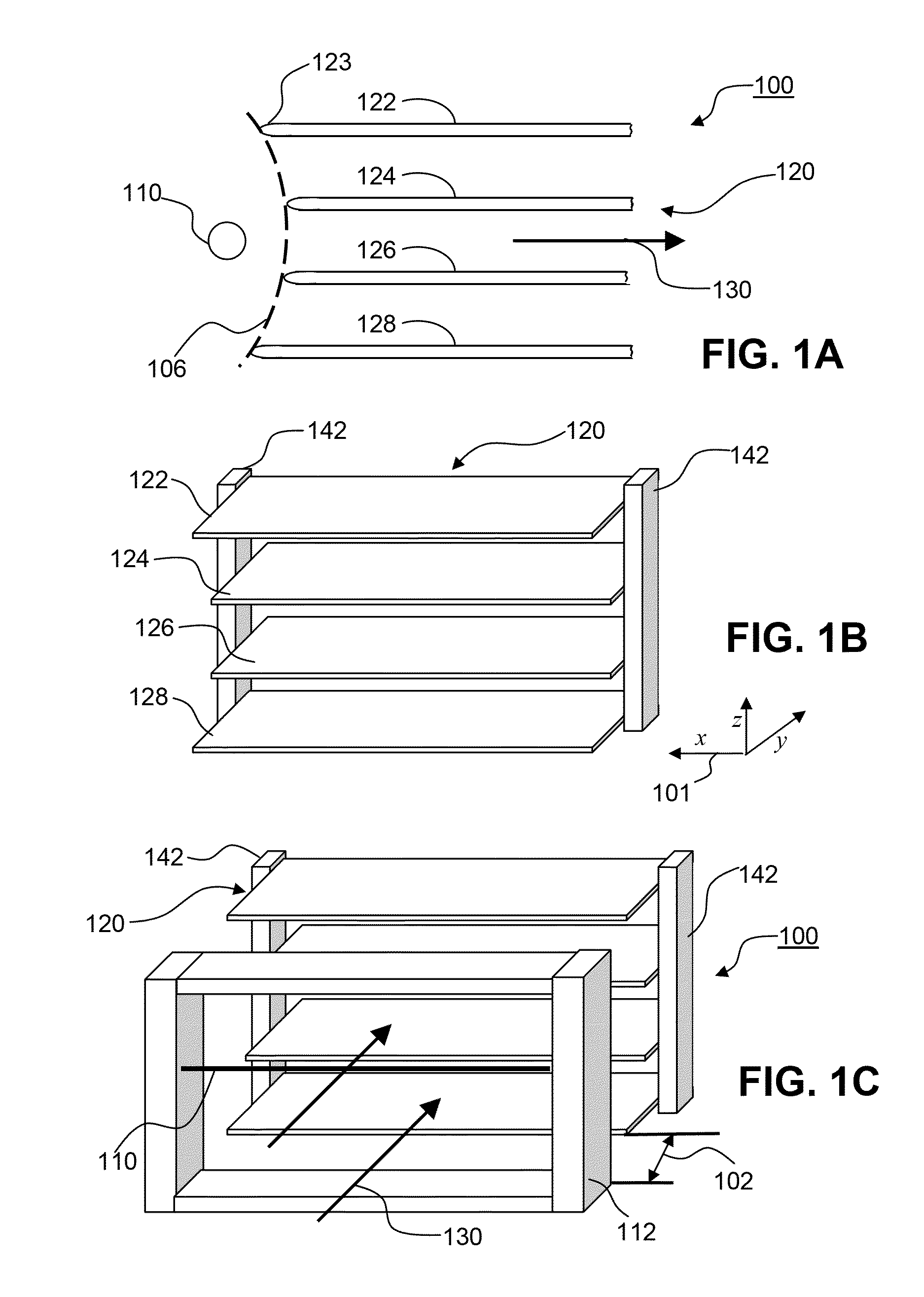
[0062]FIG. 1A is a cross-sectional view of an EHD device 100 comprising corona discharge electrode 110 and collector electrode array 120. Collector electrode array 120 comprises several collector electrodes 122, 124, 126 and 128 in the shape of substantially flat plates of any desirable length and thickness. Collector electrodes 124 and 126, disposed between top and bottom collector electrodes 122 and 128, are recessed away from corona discharge electrode 110 in a manner such that the ends of the collector electrodes form a generally curved shape 106. Each collector electrode is illustrated as having a rounded end 123, which may reduce the strength of the electric field in this area of the collector electrode and beneficially promote fluid flow past collector electrode structure. It is understood, however, that the ends may have sharp edges as well. When EHD device 100 is operational, the EHD forces generated between corona discharge electrode 110 and collector electrode array 120 f...
fourth embodiment
[0072]FIG. 6D is a front perspective view of an EHD device using the collector electrode structure of FIG. 6C and illustrated as a component of a thermal management system for dissipating heat generated by one or more thermal sources. EHD device 600 comprises corona discharge electrodes 110 and collector electrode array 620 of plural collector electrodes 626 of FIG. 6C. Collector electrodes 626 are made of both a thermally-conductive and electrically conductive material and function both as collector electrodes and as a heat sink. EHD device 600 further comprises thermal conduit 645 which is in thermal contact with collector electrodes 626. Thermal conduit 645 transports heat from a thermal source in the general direction or small arrows 647 to collector electrodes 626 of array 620. The extent of the path and configuration of thermal conduit 645 from the thermal source are omitted. In operation, EHD device 600 generates EHD forces in the direction of arrow 630 to move ambient air in...
fifth embodiment
[0073]FIG. 7A is a top plan view of an EHD device comprising an array of corona discharge electrodes 710 and an array 720 of collector electrodes. Individual collector electrodes 721 are supported by at least one support member 714. Frame members 712 support corona discharge electrodes disposed in parallel with the collector electrodes 720. While EHD device 700 is illustrated as having a relatively shallow depth (in the y direction), it is understood that EHD device 700 may be configured in a variety of aspect ratios (width-to-height relationships) to suit a particular purpose. In operation, EHD device 700 generates EHD forces in the downward z direction to move a fluid in the vicinity of the EHD device between collector electrodes 720. FIG. 7B is a cross-sectional view of the EHD device of FIG. 7A taken at dashed line 702 of FIG. 7A, and illustrating fluid flow direction 730. It can be seen from this view that the height of the collector electrodes varies in a pattern. For example,...
PUM
 Abstract
Description
Claims
Application Information
 - R&D
- Intellectual Property
- Life Sciences
- Materials
- Tech Scout
- Unparalleled Data Quality
- Higher Quality Content
- 60% Fewer Hallucinations
Browse by: Latest US Patents, China's latest patents, Technical Efficacy Thesaurus, Application Domain, Technology Topic, Popular Technical Reports.
© 2025 PatSnap. All rights reserved.Legal|Privacy policy|Modern Slavery Act Transparency Statement|Sitemap|About US| Contact US: help@patsnap.com


