Proximity detection system for deep wells

a detection system and deep well technology, applied in the direction of survey, directional drilling, borehole/well accessories, etc., can solve the problems of virtually impossible to know the exact location of the well at a given depth, severe difficulties, and difficult to precisely control the path followed by the well, etc., to achieve accurate calculations

Active Publication Date: 2010-06-24
HALLIBURTON ENERGY SERVICES INC
View PDF5 Cites 71 Cited by
  • Summary
  • Abstract
  • Description
  • Claims
  • Application Information

AI Technical Summary

Benefits of technology

[0014]Briefly, the present invention is directed to an improved method and apparatus for determining the distance and direction from the drill bit of a drill string in a borehole being drilled to a target location, such as the center of an existing borehole casing, without the need to withdraw the drill string to make the necessary measurements, by making magnetic field measurements from a drill bit sub, or drill head at the bottom of the relief well and communicating those measurements to the surface so that accurate calculations can be made.
[0019]In a second embodiment of the invention, the drill string incorporates at least one, and preferably two spaced electrode sections that are electrically isolated from the remainder of the drill string, includes a conventional MWD instrument mounted above a directional drilling steering assembly which may incorporate a hydraulic drive motor, as discussed above, and includes a drill head mounted on a bent sub and driven by the motor, with a magnetic field sensor instrument mounted on the drill head. In this embodiment, the need for a wireline that can be lowered down the center of the drill stem is eliminated. In its place is a downhole instrument package incorporating suitable telemetry such as transmit / receive communications electronics and located in a nonmagnetic section of the drill string for communicating with the drill head instrument. This instrument package also includes a down-hole electrode power supply such as a battery pack, an alternator, or both, with the power supply being connected through suitable cables to the drill string electrode or electrodes for current injection from the down-hole power source. The drill head sensor instrument includes suitable telemetry such as transmitter and receiver electronics for communicating with the transmit / receive electronics in the down-hole instrument package, which, in turn, communicates with a standard MWD instrument that is also located in the nonmagnetic section. The MWD instrument communicates with surface receivers in conventional manner, as by way of pressure pulses in the drilling fluid, to enable data transfer and control signals to pass between instrumentation at the surface and the drill head sensor instrument.
[0020]In another embodiment of the invention, magnetic field measurement accuracy may be improved in some circumstances by operating the system in a pulsed transient mode, wherein the earth formations surrounding the relief and the target wells are energized by a stepped, or pulsed, primary excitation current from a power source, which may be either at the surface or downhole. Measurements of magnetic fields produced by the resulting current flow in the target are made at the drill head sensor instrument immediately following a stepwise turn-off of the excitation current, when that current is zero. Each pulse of electrical energy supplied to the electrodes causes a current to flow through the earth's formations to the target, and, as described in the foregoing U.S. Pat. No. 4,700,142, this current is collected on the electrically conductive target. The resulting target current flow creates a characteristic target magnetic field that is detected by the drill head sensor instrument. In the pulsed, or transient, mode of operation of this embodiment, the magnetic field measurement is made after the primary energizing current stops, so that the magnetic fields that are measured will be entirely due to eddy currents. That is, when the excitation current is stepped to zero, measurements are made of the magnetic fields produced by a decaying target well current flow due to induction effects in the target / earth system. Although this decay current produces only a very small field, since even the primary target current typically is only a few percent of the energizing current, the measurement of the decay field is more accurate, since interfering fields caused by the primary electrode current in the earth are not present. Although use of a single downhole drill string electrode is feasible, the above-described transient pulsed current magnetic field measurement benefits greatly from the use of at least two vertically spaced, electrically isolated conductive drill string pipe electrode sections, each separated from each other and other adjoining pipe sections by one or more electrically insulating subs.

Problems solved by technology

It is well known that in drilling boreholes in the earth, such as deep wells for oil and gas exploration, precise control of the path followed by the well is extremely difficult, so that it is virtually impossible to know the exact location of the well at a given depth.
This is not of particular concern in many drilling operations, but if drilling precision is necessary, as where a borehole is to be drilled precisely to intersect a target location, is to be drilled so as to avoid an existing well, or is to be drilled to be parallel to an existing borehole, such variations can cause severe difficulties.
In order to do this, the relief well must be drilled to intersect the original well at the desired level, and since such ruptures, or blowouts, often produce extremely hazardous conditions at the surface in the vicinity of the original well, the relief well usually must be started a considerable distance away from the original wellhead and drilled at an incline down to the desired point of intersection.
Because the same problems of control of the direction of drilling that were encountered in the original well are also encountered in drilling the relief well, the location of the relief well borehole also cannot always be known with precision as the relief well is being drilled; accordingly, it is extremely difficult to determine the distance and direction from the end of the relief well to the desired point of intersection on the target well.
In addition, the relief well usually is very complex, compounding the problem of knowing exactly where it is located with respect to a target that may be 10 inches in diameter at a distance of thousands of feet below the earth's surface.
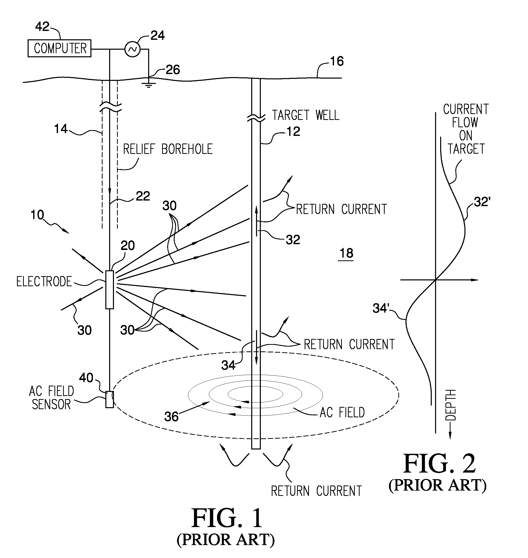
Some utilized surveying techniques to locate the relief well with respect to a target well, but such survey techniques are not capable of providing accurate data concerning the relationship of the relief well to the original well until the relief well has approached very near the original well.
Magnetic gradient ranging equipment can be used with considerable accuracy at close range; however, it has been found that outside a radius of a few tens of feet, such systems are usually inadequate.
Some of these systems are directed to the measurement of the apparent resistivity of the earth across a pair of electrodes but, since no directionality is given by this method, it is ineffective for directing a relief well with respect to an existing well.
However, such systems do not suggest the possibility of locating relatively small targets such as well bores.
However, such systems do not operate when there is no sound emanating from the target well, and, in addition, do not provide the required degree of directional and distance accuracy.
In such a system, however, the target well must be accessible so that the signal source can be placed in one well and the receiver in the other, and is not effective where the target well is not open.
Since the drill string for the relief well must be pulled for each measurement, the drilling of a relief well becomes very expensive, especially in off-shore drilling, wherein more time may be spent measuring than is spent drilling.
The foregoing systems are widely, and successfully, used; however, the need for time-consuming periodic withdrawals of the drill string so that suitable sensors and electrodes for generating the ground current can be lowered into place to obtain distance and direction measurements from the relief well is a drawback, since a drilling rig operation can cost upwards of $500,000.00 per day in offshore drilling operations.
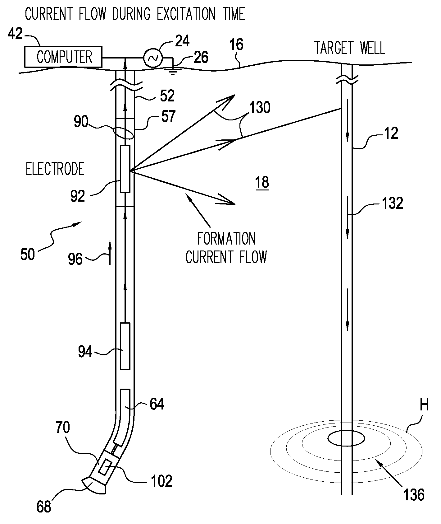
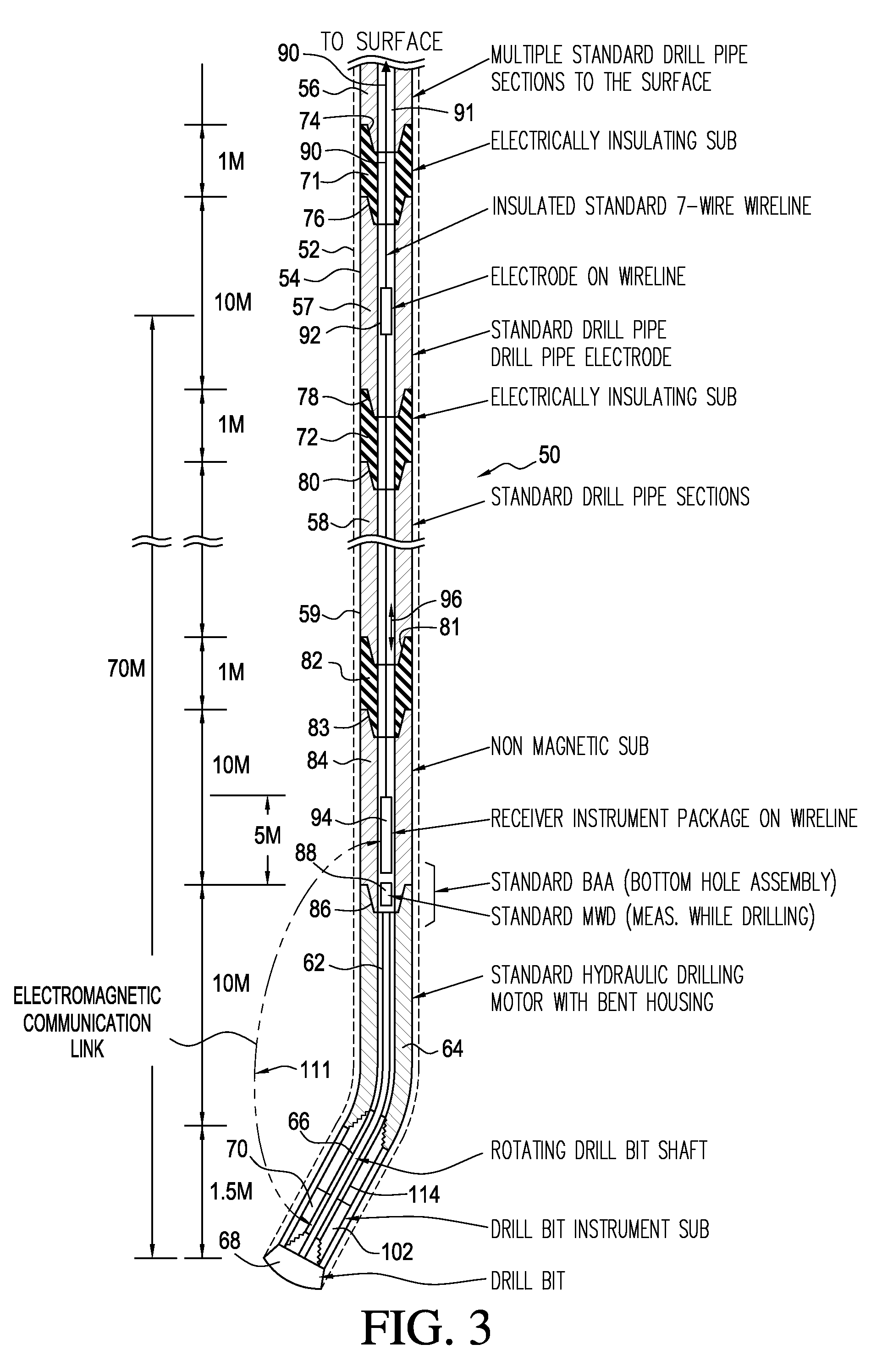
Another difficulty encountered in typical borehole drilling operations such as those described above is that the path of the borehole, which may be a relief well as described above, is tracked during drilling by a “measurement while drilling” (MWD) instrument that is mounted near, but not at, the bottom of the drill string.
As a result of this, the MWD instrument is typically located 10-20 meters above the face of the drill bit, so that when magnetic field measurements are made with the drill string in the relief well, they are actually made a considerable distance from the drill bit, introducing a significant error in determination of the relative distance and direction of the target with respect to the drill bit.
This greatly increases the difficulty of accurately controlling the location of the borehole being drilled with respect to the target.

Method used


Image

  • Proximity detection system for deep wells
  • Proximity detection system for deep wells
  • Proximity detection system for deep wells

Examples


Embodiment Construction

[0037]Turning now to a more detailed consideration of the present invention, FIG. 1 illustrates, in diagrammatic form, a standard well locating system 10 such as that described in U.S. Pat. No. 4,700,142, the disclosure of which is hereby incorporated herein by reference. In such a system, a target well 12 is to be located by drilling a second well, or borehole 14 along a path that will approach the target at a desired depth below the earth's surface 16. As is known, the second borehole may be a rescue well that may be intended to intersect a target, may be intended to locate and avoid the target, or may be intended to locate and then be drilled along a path that is parallel the target. For simplicity, such a second borehole may be referred to herein as a relief well, it being understood that it may be drilled for any purpose. Typically the target is a cased well or has a drill string or other electrically conductive material in it, so that electrical current flowing in the earth's ...


PUM


Abstract

A method and apparatus for magnetic field measurements to determine the proximity of a nearby target incorporating electrically conductive material includes a drill string (54) having multiple drill pipe sections (56, 57, 58, 59) connected end-to-end, with at least one of the drill pipe sections (57) being electrically conductive and isolated to provide an electrode section. A nonmagnetic drill pipe section (84) is connected in the drill string below the electrode section (57), and a hydraulic motor (62) having a rotatable drill bit sub (70) carrying a magnetic field sensing instrument package (102) is connected to a lowermost end of the drill string. A power supply provides a time-varying current to the drill pipe electrode section (57) to produce a corresponding target current magnetic field to be detected at the drill bit instrument (10)2, and a communication instrument package (94) is locatable within the nonmagnetic drill pipe section (84) to receive magnetic field data from the magnetic field sensing instrument package (102) on the drill bit (70).

Description

CROSS REFERENCE TO RELATED APPLICATIONS[0001]This application is a Continuation-in-Part of U.S. application Ser. No. 12 / 342,034, filed Dec. 22, 2008, and entitled “Wireline Communication System for Deep Wells”, the entire disclosure of which is hereby incorporated herein by reference.FIELD OF THE INVENTION[0002]The present invention relates, in general, to methods and apparatus for locating a nearby conductive target, such as a cased well or borehole, from a remote location such as a second borehole or deep well to obtain data for use in guiding the direction of drilling the second well with respect to the target. More particularly, the invention is directed to methods and apparatus for injecting time-varying electrical currents into the earth from one or more electrodes in a borehole being drilled, for detecting at the drill bit of that borehole the electromagnetic field vectors resulting from the portion of such injected currents which flows in metal at the target, and for transmi...

Claims


Application Information

Patent Timeline
Patent Type & Authority Applications(United States)
IPC IPC(8): E21B47/00E21B47/01E21B47/12E21B7/04G01V3/08G01V3/26E21B47/02
CPCG01V3/24E21B47/02216E21B47/0228E21B47/13E21B47/013E21B47/024
Inventor KUCKES, ARTHUR F.
Owner HALLIBURTON ENERGY SERVICES INC
Why Eureka
Try Eureka