Organic light-emitting element and light-emitting device using the same

a technology of light-emitting elements and light-emitting devices, which is applied in the field of light-emitting elements, can solve the problems of insufficient luminous efficiency, rare light-emitting materials, and insufficient properties of materials, and achieves high luminous efficiency and favorable emission color.

Active Publication Date: 2010-06-24
CANON KK
View PDF10 Cites 12 Cited by
  • Summary
  • Abstract
  • Description
  • Claims
  • Application Information

AI Technical Summary

Benefits of technology

[0010]Accordingly, one aspect of the present invention provides an organic light-emitting element that can be produced using a variety of light-emitting materials and can exhibit a favorable emission color with a high luminous efficiency.

Problems solved by technology

If the PL spectrum is different from the spectrum of the desired color to be extracted, luminous efficiency may not be obtained sufficiently.
However, light emitting materials are very rare which have PL spectra substantially the same as the spectrum of a desired color to be extracted from the element.
Even such materials do not always satisfy properties other than emission color, such as lifetime and luminous efficiency.

Method used


Image

  • Organic light-emitting element and light-emitting device using the same
  • Organic light-emitting element and light-emitting device using the same
  • Organic light-emitting element and light-emitting device using the same

Examples


example 1

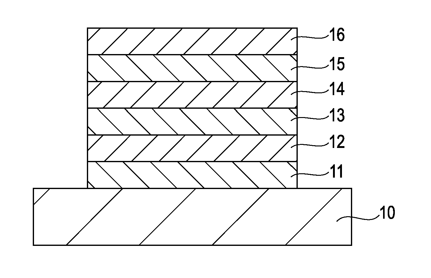
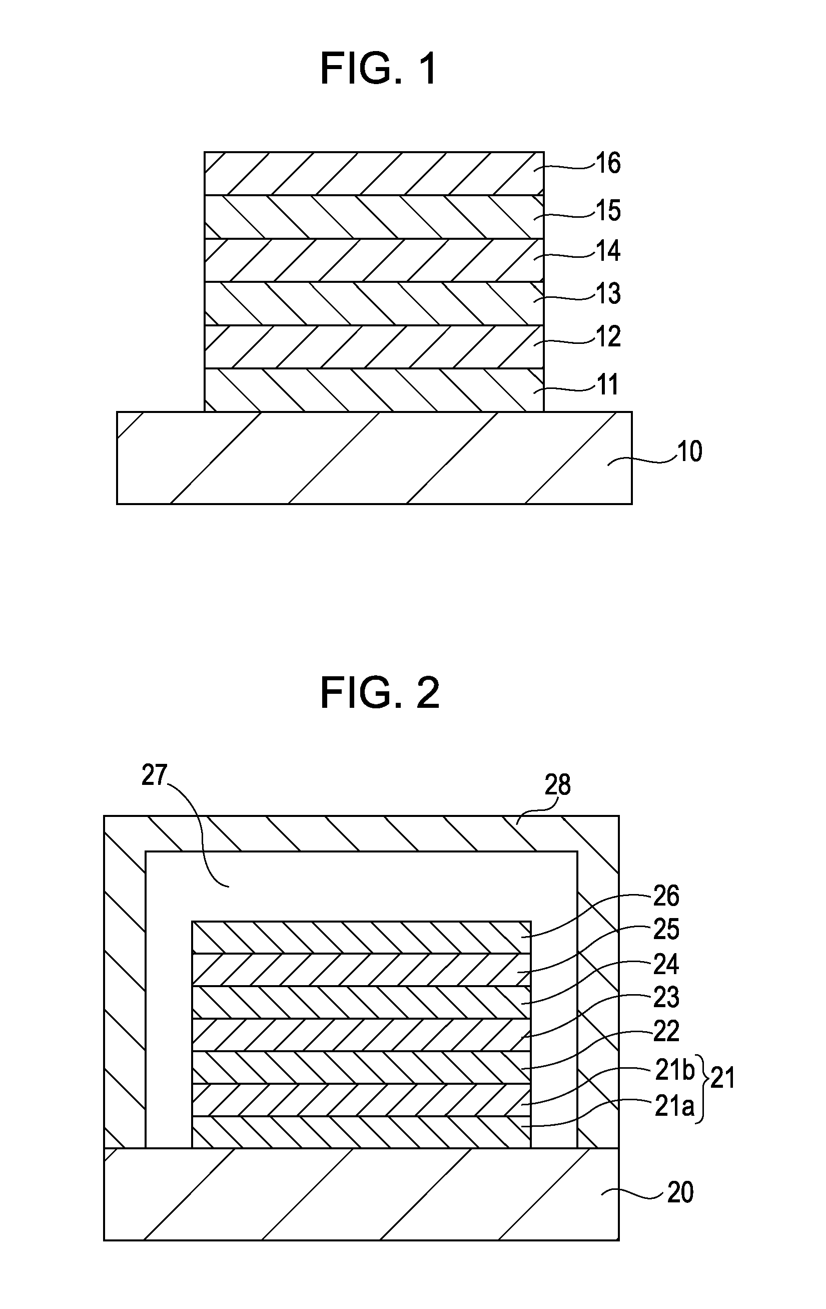
[0073]An organic light-emitting element shown in FIG. 2 was prepared in the following process.

[0074]Aluminum alloy (AlNd) was deposited to a thickness of 150 nm on a substrate 20 by sputtering to form a reflection layer 21a, and ITO was deposited to a thickness of 10 nm on the reflection layer 21a by sputtering to form a transparent electroconductive layer 21b. The resulting substrate was subjected to ultrasonic cleaning with isopropyl alcohol (IPA) and boiling cleaning, followed by drying. After UV / ozone cleaning, organic compounds were deposited by vacuum vapor deposition as below.

[0075]First, a compound expressed by Chemical Formula 1 was deposited to a thickness of 30 nm to form a hole transport layer 22 at a vacuum of 1×10⁻⁴ Pa and a deposition rate of 0.2 nm / s.

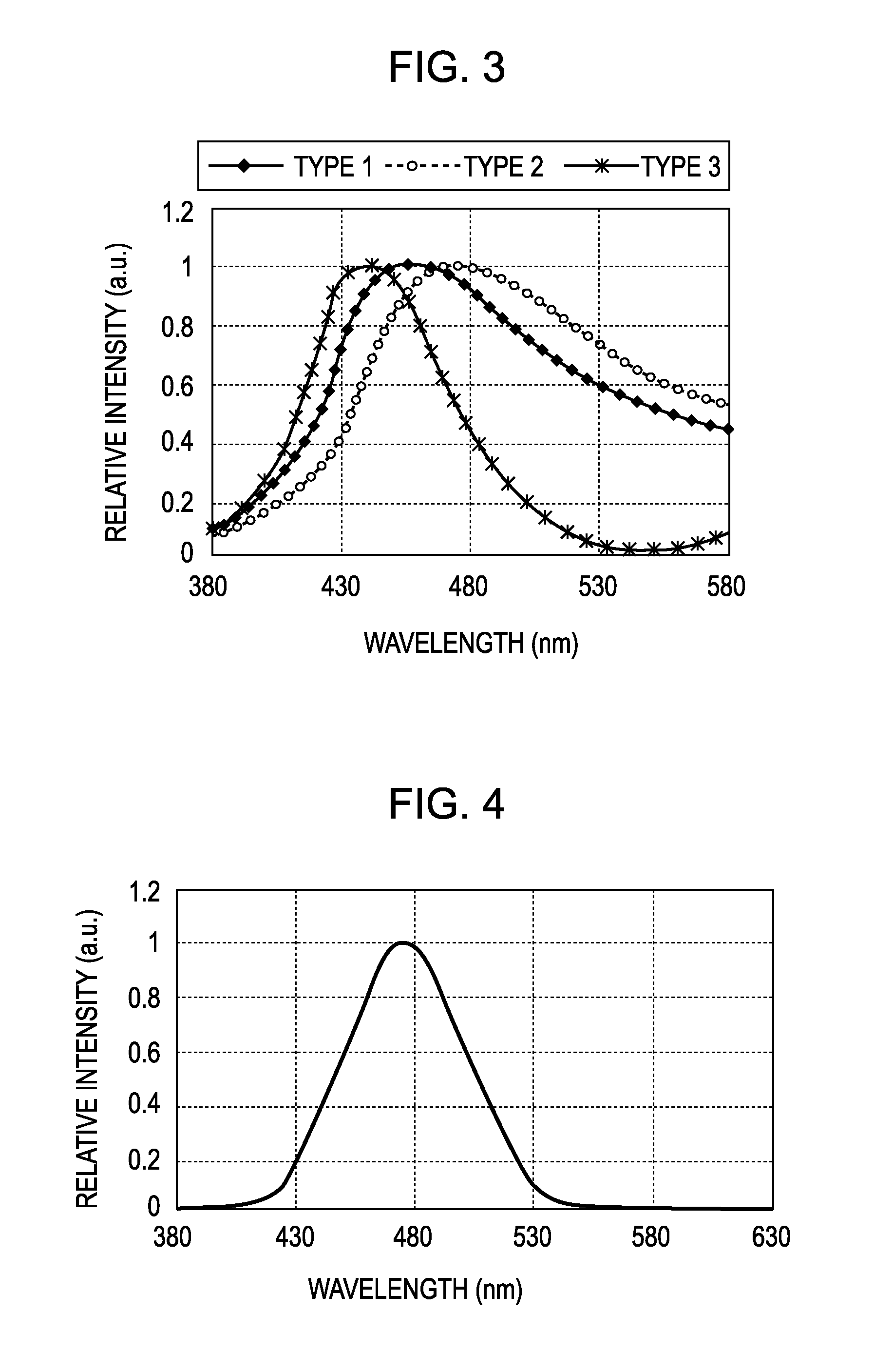
[0076]Then, a blue light-emitting layer 23 exhibiting the PL spectrum shown in FIG. 4 was formed to a thickness of 35 nm by vacuum vapor deposition at a vacuum of 1×10⁻⁴ Pa and a deposition rate of 0.2 nm / s.

[0077]Subsequ...

example 2

[0083]The organic light-emitting element of Example 2 is different from that of Example 1 in that the transparent electroconductive layer 21b and the hole transport layer 22 were formed to thicknesses of 100 nm and 52 nm, respectively. The other layers have the same thicknesses as in Example 1. Table 8 shows the light emitting characteristics of the organic light-emitting element of Example 2.

TABLE 8Luminous efficiency2.1 (cd / A)ChromaticityCIEx0.125coordinatesCIEy0.080Maximum peakInterference intensity distribution λ1440 nm wavelengthPL spectrum λ2475 nm EL spectrum λ3460 nm Difference in peak|λ2 −λ1|35 nmwavelength|λ2 −λ3|15 nmHalf-widthInterference intensity distribution65 nmPL spectrum46 nm

[0084]As shown in Table 8, the organic light-emitting element of Example 2 emitted a deepest blue color with CIEy of 0.08 of the luminescent chromaticity. The color of the EL spectrum extracted from the element had CIE chromaticity coordinates of (0.125, 0.080), and the deviation Δxy from the b...

example 3

[0087]The organic light-emitting element of Example 3 is different from that of Example 1 in that the reflection layer 21a was formed of a silver alloy (AgPdCu) to a thickness of 150 nm, and that the hole transport layer 22 and the electron injection layer 25 were formed to thicknesses of 124 nm and 20 nm respectively. In addition, the second electrode 26 was formed of silver, instead of ITO, to a thickness of 20 nm in a sputtering apparatus. The other layers of the element were formed of the same materials to the same thicknesses as in Example 1. Table 9 shows the light emitting characteristics of the resulting organic light-emitting element of Example 3.

TABLE 9Luminous efficiency3.2 (cd / A)Chromaticity coordinatesCIEx0.108CIEy0.116Maximum peakInterference intensity distribution λ1460 nmwavelengthPL spectrum λ2476 nmEL spectrum λ3468 nmDifference in peak|λ2 −λ1| 16 nmwavelength|λ2 −λ3| 8 nmHalf-widthInterference intensity distribution 46 nmPL spectrum 46 nm

[0088]As shown in Table 9,...


PUM


Abstract

An organic light-emitting element includes a first electrode, a second electrode, and at least one organic compound layer disposed between the first electrode and the second electrode. The organic compound layer includes a light-emitting layer containing a light-emitting material and being configured to emit light toward the first electrode and the second electrode. The light emitted toward the first electrode is reflected from a reflection plane located at the first electrode to cause interference with the light emitted toward the second electrode. The interference provides an interference intensity distribution having a maximum peak at a wavelength λ1. The light-emitting material of the light-emitting layer exhibits a photoluminescence spectrum having a maximum peak at a wavelength λ2. The organic light-emitting element produces an electroluminescence spectrum having a maximum peak at a wavelength λ3. These wavelengths satisfy the relationships: λ2≠λ3 and |λ2−λ3|<|λ2−λ1|.

Description

BACKGROUND OF THE INVENTION[0001]1. Field of the Invention[0002]The present invention relates to a light-emitting element including an organic compound layer, and more specifically to an organic light-emitting element including at least one organic compound layer that is disposed between a pair of electrodes and includes a light-emitting layer emitting light by applying a current to the organic compound layer. The present invention also relates to a light-emitting device including the organic light-emitting element.[0003]2. Description of the Related Art[0004]Organic light-emitting elements (hereinafter simply referred to as elements in some cases) have recently been studied and developed intensively. Such an organic light-emitting element includes a pair of electrodes acting as an anode and a cathode, and at least one organic compound layers including a light-emitting layer between the pair of electrodes. Each organic compound layer has a thickness of several tens of nanometers. On...

Claims


Application Information

Patent Timeline
Patent Type & Authority Applications(United States)
IPC IPC(8): H01L51/50H01L33/00H05B44/00
CPCH01L27/3211H01L51/5265H01L51/0059H10K59/35H10K85/631H10K50/852
Inventor HASEGAWA, TOSHINORINAKAMURA, NAOTOYAJIMA, MASATOWATANABE, RYOTA
Owner CANON KK
Why Eureka
Try Eureka