Optical head and optical disc device

a technology of optical discs and optical heads, applied in the field of optical heads, can solve the problems of numerical apertures that cannot be set to 0.45, inability to record/play back information in/from cds, etc., and achieve stable compatible playback and compact and inexpensive effects

Active Publication Date: 2010-06-24
PANASONIC CORP
View PDF15 Cites 10 Cited by
  • Summary
  • Abstract
  • Description
  • Claims
  • Application Information

AI Technical Summary

Benefits of technology

[0023]The invention is to solve the problems in the prior arts as discussed above, and has an object to provide a compact and inexpensive optical head that enables stable compatible playback and compatible recording among optical discs of different kinds with the use of a single objective lens.
[0025]According to this configuration, it is possible to record / play back information in a stable manner with the use of the objective lens formed of the diffraction element and the refracting lens by forming the diffraction grating in such a manner that a change of the diffraction angle in response to a change of the wavelength becomes constant even when the diffraction orders of light are changed in plural regions where the apertures are limited by the diffraction element, thereby allowing light respectively having different wavelengths to be converged onto optical discs respectively having different protective layer thicknesses at the corresponding suitable numerical apertures. It is thus possible to achieve a compact and inexpensive optical head capable of correcting spherical aberration resulting from a difference in thickness of the protective layers with the use of a single objective lens without the need for aperture limiting means, such as an optical filter, and thereby enabling stable compatible playback and compatible recording with discs of different kinds.

Problems solved by technology

The respective prior arts described above, however, have the following problems.
In the first prior art, it is possible to record / play back information in / from a BD and a DVD with the use of a single objective lens; however, it is impossible to record / play back information in / from a CD.
However, because the wavelength is almost twice as long as 405 nm, the thickness of the most suitable protective layer becomes almost as thick as the protective layer of a BD, which makes it impossible to record / play back information in / from a CD.
Further, because the aperture limiting means is absent for light used for recording / playing back information in / from a CD, the numerical aperture cannot be set to 0.45.
However, because the diffraction element and the wavelength-selective phase plates are provided with the wavelength selectivity for three wavelengths, the grooves become deeper and a loss of light amount is increased by a diffraction loss on the groove inclined planes and an error of groove depths.
This makes it impossible to secure sufficient manufacturing accuracy for a diffraction element to which the accuracy one order of magnitude smaller than the wavelength is required.
The mass of a movable portion in the actuator that drives the optical head is consequently increased, which not only makes the driving at high double speeds for focusing and tracking difficult, but also brings disadvantages in terms of costs.
This poses problems that not only the number of components is increased, but also a size reduction of the optical head becomes difficult.
In addition, the need for the switching mechanism makes a size reduction of the device more difficult.
However, because the diffraction orders of the diffraction element are changed, when the wavelength changes from the design wavelength, the converging performance is deteriorated.
However, because the diffraction order of the light beam 84 changes from the first order to the second order, a change of the diffraction angle in response to a change of the wavelength between the inner peripheral portion and the intermediate peripheral portion cannot be made constant unless the pitch of the diffraction grating in the intermediate peripheral portion is set to twice the pitch designed as the first-order diffracted light.
Hence, when the diffraction orders change for the both light beams, a change of the diffraction angle cannot be made constant, which makes it impossible to converge a light beam to a single point when the wavelength changes.

Method used


Image

  • Optical head and optical disc device
  • Optical head and optical disc device
  • Optical head and optical disc device

Examples


first embodiment

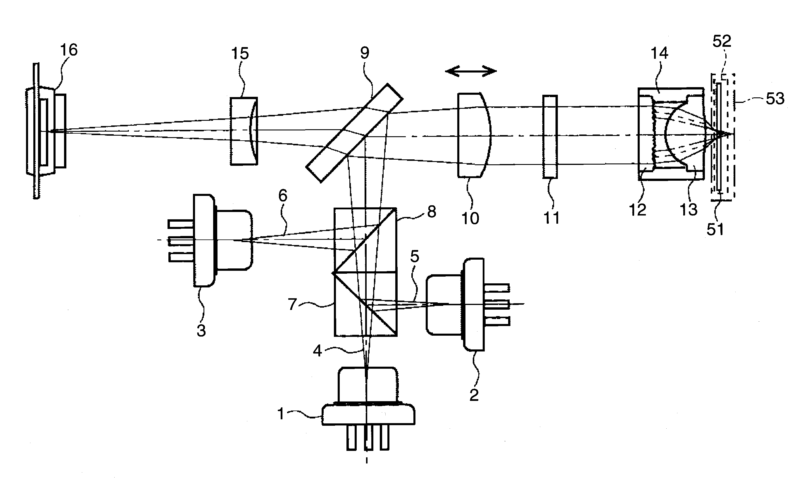
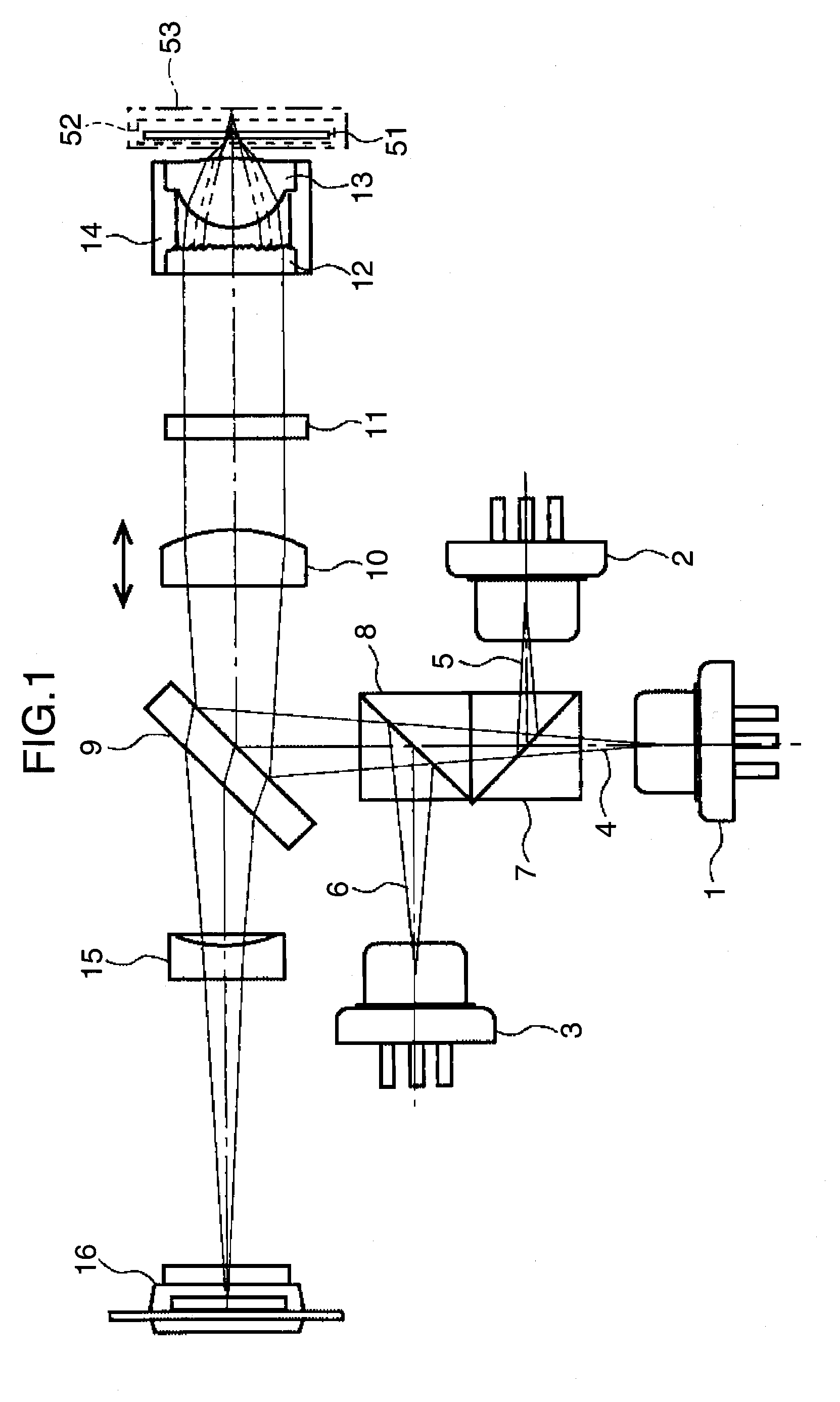
[0056]FIG. 1 is a cross section showing the overall configuration of an optical head according to a first embodiment of the invention. Referring to FIG. 1, numeral 1 denotes a blue laser light source that emits light having a wavelength λ1 (almost 405 nm), numeral 2 denotes a red laser light source that emits light having a wavelength λ2 (almost 655 nm), and numeral 3 denotes an infrared light source that emits light having a wavelength λ3 (almost 780 nm). Numeral 10 denotes a collimator lens and numeral 14 denotes an objective lens. The objective lens 14 is formed of a diffraction element 12 and a refracting lens 13. Numeral 51 denotes an optical disc having a protective layer thickness t1 of about 0.1 mm, and it is an optical information medium in / from which information is recorded / played back with a light beam having the wavelength λ1 at a numerical aperture NA1, for example, an optical disc used as a BD. Numeral 52 denotes an optical disc having a protective layer thickness t2 o...

second embodiment

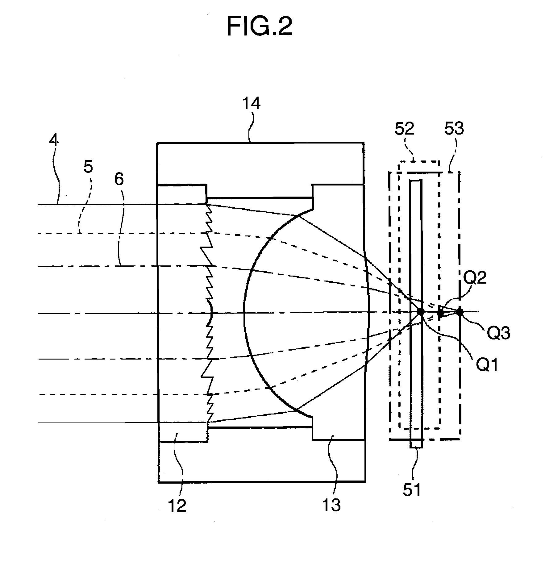
[0105]A second embodiment of the invention will now be described. In FIG. 2 used to describe the first embodiment above, the chromatic aberration, in particular, the wavelength dependence of the focal distance is cancelled out by providing the convex lens action to the diffraction element. However, because it is configured to correct the spherical aberration of optical discs each having a different protective layer by exploiting a difference of the wavelengths, the spherical aberration is generated when the wavelength varies from the design wavelength.

[0106]The configuration to correct this spherical aberration will be described using FIG. 8 and FIG. 9. FIG. 8 is an enlarged cross section showing an example of an objective lens according to the second embodiment of the invention. Referring to FIG. 8, an objective lens 143 of this embodiment is formed of a diffraction element 123 and a refracting lens 133, and has a configuration in which the refracting lens 13 of the first embodimen...

third embodiment

[0121]A third embodiment of the invention will now be described. FIG. 14 is a cross section showing the overall configuration of an optical head according to a third embodiment of the invention. Referring to FIG. 14, numeral 21 denotes a blue laser light source that emits light having a wavelength λ1 (almost 405 nm) and numeral 22 denotes a double-wavelength laser light source that emits light having a wavelength λ2 (almost 655 nm) and light having a wavelength λ3 (almost 780 nm). Numeral 28 denotes a diffraction lens that has both the diffracting action and the refracting action and acts as a convex lens. Numeral 30 denotes a collimator lens and numeral 34 denotes an objective lens. The objective lens 34 is formed of a diffraction element 32 and a refracting lens 33.

[0122]Numeral 54 denotes an optical disc having a protective layer thickness t1 of about 0.6 mm and it is an optical information medium in / from which information is recorded / played back with a light beam having the wave...


PUM

PropertyMeasurementUnit
thickness t3aaaaaaaaaa

Abstract

A compact and inexpensive optical head that enables stable compatible playback and compatible recording with optical discs of different kinds with the use of a single objective lens is achieved. The order of diffracted light at which the diffraction efficiency by a diffraction element forming the objective lens becomes the maximum is set to the third order for blue light, the second order for red light, and the second order for infrared light in the inner peripheral portion of the diffraction element, and to the sixth order for blue light, the fourth order for red light, and the third order for infrared light to limit the aperture for infrared light in the intermediate peripheral portion. In the outer peripheral portion, the aperture for red light is limited by setting the order to an integer other than multiples of 3 for blue light.

Description

TECHNICAL FIELD[0001]The present invention relates to an optical head that records, plays back, or erases information in or from an optical information storage medium, such as an optical disc, an objective lens used in the optical head, an optical disc device employing the optical head, a computer to which the optical disc device is applied, and a system, such as an optical disc recorder, that records and plays back a video / sound signal in and from an optical information storage medium using the optical disc device.BACKGROUND ART[0002]Regarding a compact disc (hereinafter, abbreviated to CD) deemed as the first generation of optical discs, information is recorded in or played back from (hereinafter, referred to as recorded in / played back from) an optical disc having a 1.2-mm-thick protective layer by setting the numerical aperture of the objective lens to 0.45 to 0.5 and using infrared light having a wavelength of 780 nm. In the present specification, the protective layer is defined...

Claims


Application Information

Patent Timeline
Patent Type & Authority Applications(United States)
IPC IPC(8): G11B7/135G11B7/125
CPCG02B5/1814G02B27/4238G02B27/4277G11B2007/0006G11B7/1353G11B7/1374G11B7/1275
Inventor MIZUNO, SADAO
Owner PANASONIC CORP
Why Eureka
Try Eureka