Base fabric for airbag, airbag and method for production of the same

a technology for airbags and base fabrics, applied in the direction of vehicular safety arrangements, pedestrian/occupant safety arrangements, synthetic resin layered products, etc., can solve the problems of unfavorable weight saving, inconvenient operation, and inconvenient use, so as to improve productivity, simplify the steps, and the effect of simple operation

Inactive Publication Date: 2010-06-24
TOYOTA BOSHOKU KK +1
View PDF4 Cites 13 Cited by
  • Summary
  • Abstract
  • Description
  • Claims
  • Application Information

AI Technical Summary

Benefits of technology

[0008]The present invention has been achieved in view of the above-described conventional situations, and an objective thereof is to provide a lightweight base fabric for an airbag that has an equally sufficient strength and the like in an oblique direction as the cases in vertical and lateral directions when three pieces, particularly four pieces of the fibrous bodies are laminated and oriented direction of the fibers constituting the fibrous bodies are differed, and that has a highly isotropy; a highly strong and lightweight airbag using the same; and a method for the production of an airbag in which steps are simplified and which offers a high productivity.
[0010]In the present invention, a base fabric for an airbag has a sufficient strength and the like, and is lightweight since plural fibrous bodies configured by fibers that are oriented in one direction are laminated and an oriented direction of the fibers in one fibrous body out of two fibrous bodies that are adjacently laminated is different from an oriented direction of the fibers in the other fibrous body. In addition, laminated fibers are not bent—unlike a woven fabric—and thus, as compared to a woven textile having the same length, the yarn length (fiber length) that is consumed is shorter. Therefore, weight-saving can be easily achieved, and the strength of the fiber is not decreased due to internal stress occurring by bending. Moreover, when three or more fibrous bodies, particularly four or more fibrous bodies, are laminated while setting the fibrous bodies so that orienting directions of the respective fibers constituting each of the fibrous bodies are differed, a base fabric having an equivalent strength and expansion not only in a vertical direction and a lateral direction but also in an oblique direction can be achieved. Unlike a base fabric using the conventional plain weave fabric, a base fabric of the present invention can be one having no anisotropy, that is, one having at least a low anisotropy. Therefore, the flexibility of cutting is increased, and the yield can be improved. In addition, since the orienting direction of the fiber can be arbitrarily set, the orienting direction can be set to a direction optimal for each product.
[0012]According to the airbag of the present invention, it has a highly strength and is lightweight because it is produced using the above base fabric for an airbag of the invention.
[0014]According to the method for the production of an airbag of the present invention, a weaving step and a refining step by a loom, which are necessary in the conventional technology, are rendered unnecessary, and thus, the operation is simple, the steps are simplified, and the productivity can be improved. Moreover, since the method does not comprise a process for weaving with a loom, a load applied to fibers during the production can be decreased, and thus, the strength, expansion and the like, originally inherent in the fiber are not impaired.

Problems solved by technology

Moreover, since the yarn is bent, a required yarn length is longer than the length of a fabric, which is unfavorable in view of weight-saving.
Furthermore, while a plain weave fabric has a sufficient strength and the like in two directions, i.e., a vertical direction and a lateral direction, it does not necessarily have the equal strength and the like, in an oblique direction.
In this manufacturing method, the operation becomes complicated in that it is necessary to perform highly-dense hollow weaving by using a loom, and further, refinery is necessary, for example, and also, the number of steps is large.
Thus, it is difficult to say that the productivity is high.

Method used


Image

  • Base fabric for airbag, airbag and method for production of the same
  • Base fabric for airbag, airbag and method for production of the same
  • Base fabric for airbag, airbag and method for production of the same

Examples


example

[0043]Hereinafter, the invention will be more specifically described using figures.

1. Configuration of Base Fabric for Airbag

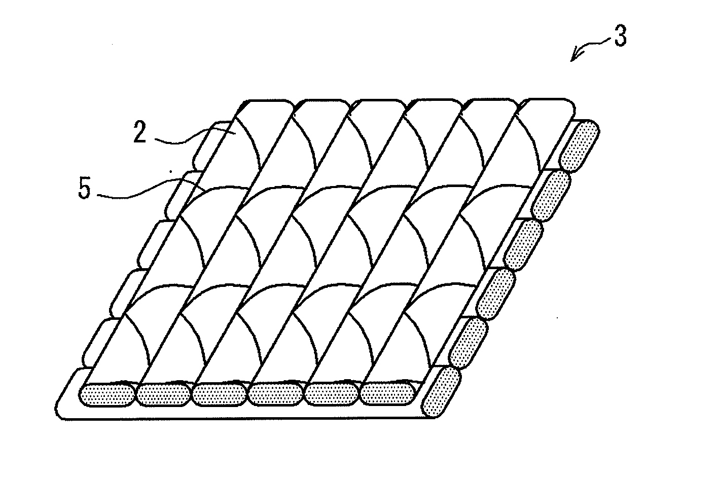
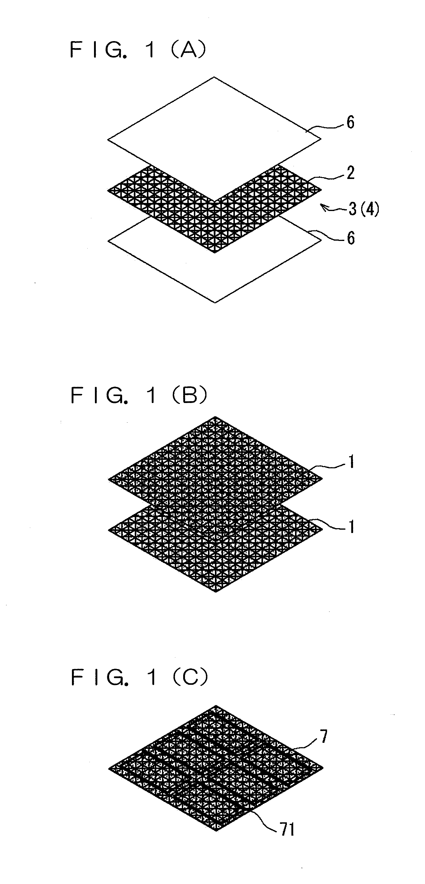
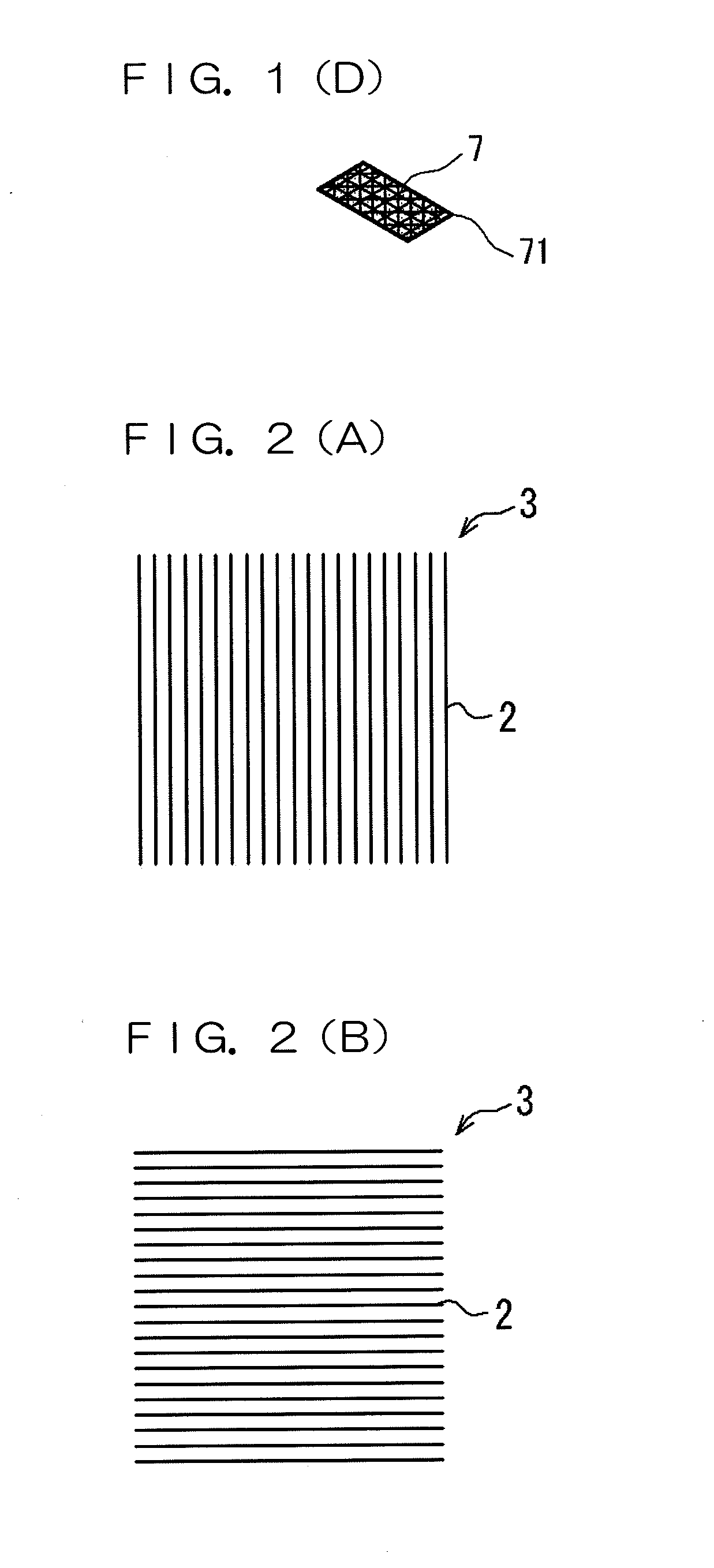
[0044]A base fabric for an airbag 1 according to the embodiment is provided with a fibrous laminate 4 shown in FIG. 2(E) in which plural fibrous bodies 3 configured by fibers 2 that are oriented in one direction are laminated. In the fibrous laminate 4, an oriented direction of the fibers 2 in one fibrous body 3 out of two fibrous bodies 3 that are adjacently laminated is different from an oriented direction of the fibers 2 in the other fibrous body 3. Herein, four pieces of the fibrous bodies 3 [FIGS. 2(A) to (D)] are laminated, and unidirectionally orienting directions of the fibers 2 constituting each of the fibrous bodies 3 respectively form an angle of substantially 45 degrees and they are spaced at substantially equal intervals [FIG. 2(E)].

[0045]The cover factor of the fibrous laminate 4 was 1729.

[0046]The fiber 2 constituting the fibrous body 3 is made ...


PUM

PropertyMeasurementUnit
angleaaaaaaaaaa
angleaaaaaaaaaa
angleaaaaaaaaaa

Abstract

The base fabric for an airbag of the present invention comprises a fibrous laminate in which plural fibrous bodies configured by fibers that are oriented in one direction are laminated, and an oriented direction of the fibers in one fibrous body out of two fibrous bodies that are adjacently laminated is different from an oriented direction of the fibers in the other fibrous body. The airbag of the present invention comprises the base fabric for an airbag and is obtained by a method including joining step for joining the plural base fabrics for an airbag so that an internal space having a predetermined shape is formed and cutting step for cutting along a joint section formed by the joining step.

Description

INCORPORATION BY REFERENCE[0001]The present application claims priority under 35 U.S.C. §119 of Japanese Patent Application No. 2008-326543, filed on Dec. 22, 2008, the disclosure of which is expressly incorporated by reference herein in its entirety.BACKGROUND OF THE INVENTION[0002]1. Field of the Invention[0003]The present invention relates to a base fabric for an airbag used for the production of an airbag that is expanded during a vehicular collision so as to absorb and alleviate an impact applied to a passenger, an airbag using the same, and a method for the production of an airbag. More particularly, the present invention relates to a lightweight base fabric for an airbag that has an equally sufficient strength and the like in an oblique direction as the cases in vertical and lateral directions when three pieces, particularly four pieces of the fibrous bodies are laminated and oriented direction of the fibers constituting the fibrous bodies are differed, and that has a highly ...

Claims


Application Information

Patent Timeline
Patent Type & Authority Applications(United States)
IPC IPC(8): B32B5/12B32B37/00
CPCB60R21/235Y10T428/24074B60R2021/23523B32B7/12B32B27/12B32B27/32B32B37/04B32B37/185B32B2260/021B32B2260/046B32B2262/0253B32B2305/18B32B2307/558B32B2307/724B32B2605/00Y10T428/249921
Inventor TAKAGI, NATSUHIKOSAKAI, AKIHITOMORI, HIROMASAKAWAZOE, SATOSHIITO, TAKAHIRO
Owner TOYOTA BOSHOKU KK
Why Eureka
Try Eureka