LNG tanker and method for marine transportation of LNG

a technology of liquefied natural gas and tanker, which is applied in the direction of special-purpose vessels, load accommodation, transportation and packaging, etc., can solve the problems of irregular shape and require laborious heat-insulating works, and achieve the effect of reducing sloshing in the membrane type, reducing sloshing, and being easy to constru

Inactive Publication Date: 2010-07-01
MORIMOTO
View PDF6 Cites 18 Cited by
  • Summary
  • Abstract
  • Description
  • Claims
  • Application Information

AI Technical Summary

Benefits of technology

[0010]An object of the present invention is to provide an LNG tanker which has higher volumetric efficiency of a tank and is easy to construct. Another object of the present invention is to reduce sloshing in membrane type of LNG tanks.
[0011]The present invention is to provide an LNG tanker in which the foremost LNG tank is of a spherical free-standing type of tank, and each of other subsequent tanks are of membrane type tanks. By making most of the LNG tanks in a membrane type in this manner, the tanker is able to have a higher volumetric efficiency and thus a larger tank capacity for the size of its hull.
[0012]The foremost LNG tank is formed in a narrow space of the fore portion of the hull. If that tank is made in membrane type, it may become of irregular shape and require laborious heat-insulating works. In the present invention, the foremost tank is made in the spherical free-standing type, the construction works are very easy and done in short period, particularly by making a spherical tank on the work shop and then mounting it on the hull. Further, the foremost spherical tank can be installed even in a narrow space with V shape cross section, thus providing a ship's bow of fine form suitable for high speed sailing.
[0013]The present invention is further to provide a method of marine transporting LNG in which LNG tanks are made in two different types, one is a membrane type and the other is a spherical free-standing type. During transport, LNG in the spherical free-standing type tank is transferred to the membrane type tank. This can make up for the loss of boil-off gas in the membrane tank and keep them nearly full of LNG, so that the sloshing problem is solved.

Problems solved by technology

If that tank is made in membrane type, it may become of irregular shape and require laborious heat-insulating works.

Method used


Image

  • LNG tanker and method for marine transportation of LNG
  • LNG tanker and method for marine transportation of LNG
  • LNG tanker and method for marine transportation of LNG

Examples


Embodiment Construction

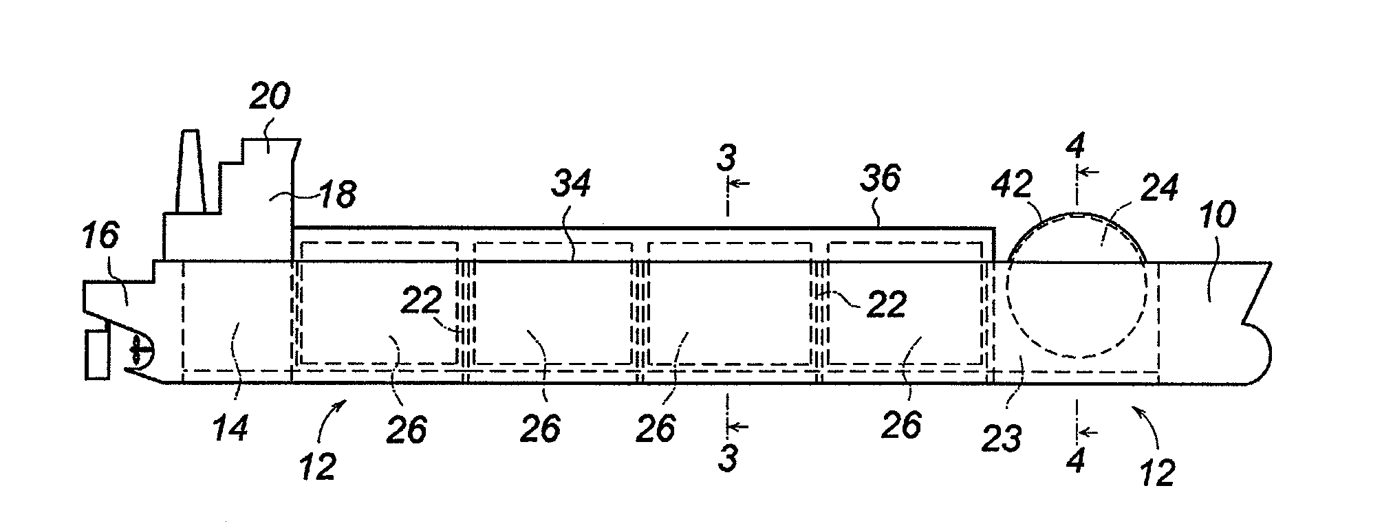
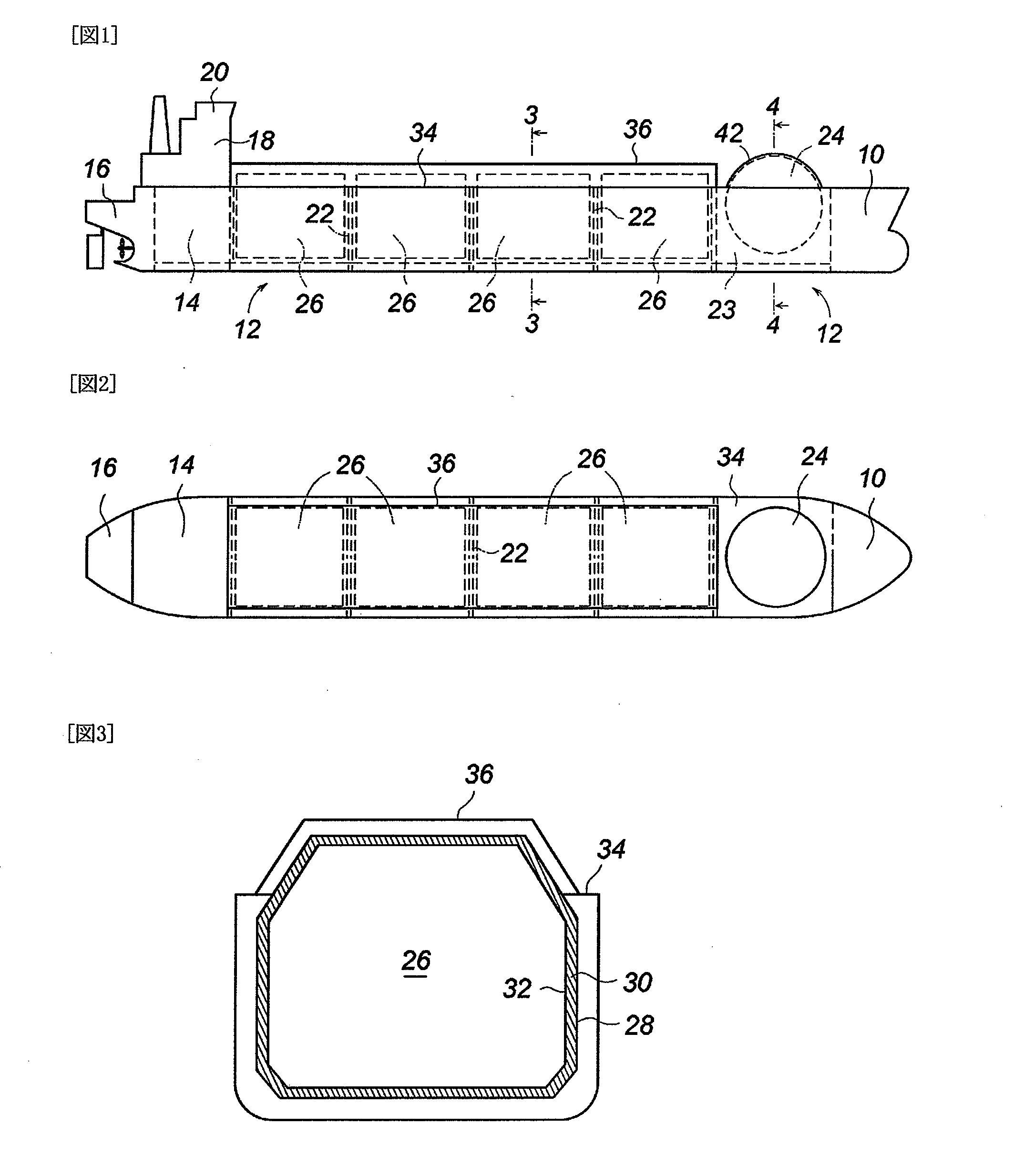
[0020]Referring now to the FIG. 1 and FIG. 2, there is shown an LNG tanker which includes a bow portion 10, a tank section 12, an engine room 14 and a stern portion 16 in succession. On the engine room stands an accommodation space 18 and a steering room 20 thereon. The tank section 12 is divided by transverse bulkheads 22 into a plurality of divisions, the foremost division 23 of which is equipped with a spherical free-standing type tank 24, and each of other subsequent divisions form membrane type tank 26.

[0021]As shown in FIG. 3, each membrane type tank 26 is surrounded by double hull structures; its inner hull 28 are covered with thermally insulation material 30, which is liquid-tightly covered by a membrane materials 32. The membrane tank 26 has a head portion which protrudes upward through an upper deck 34 to increase the tank capacity, and the head portion is covered with a trunk deck 36.

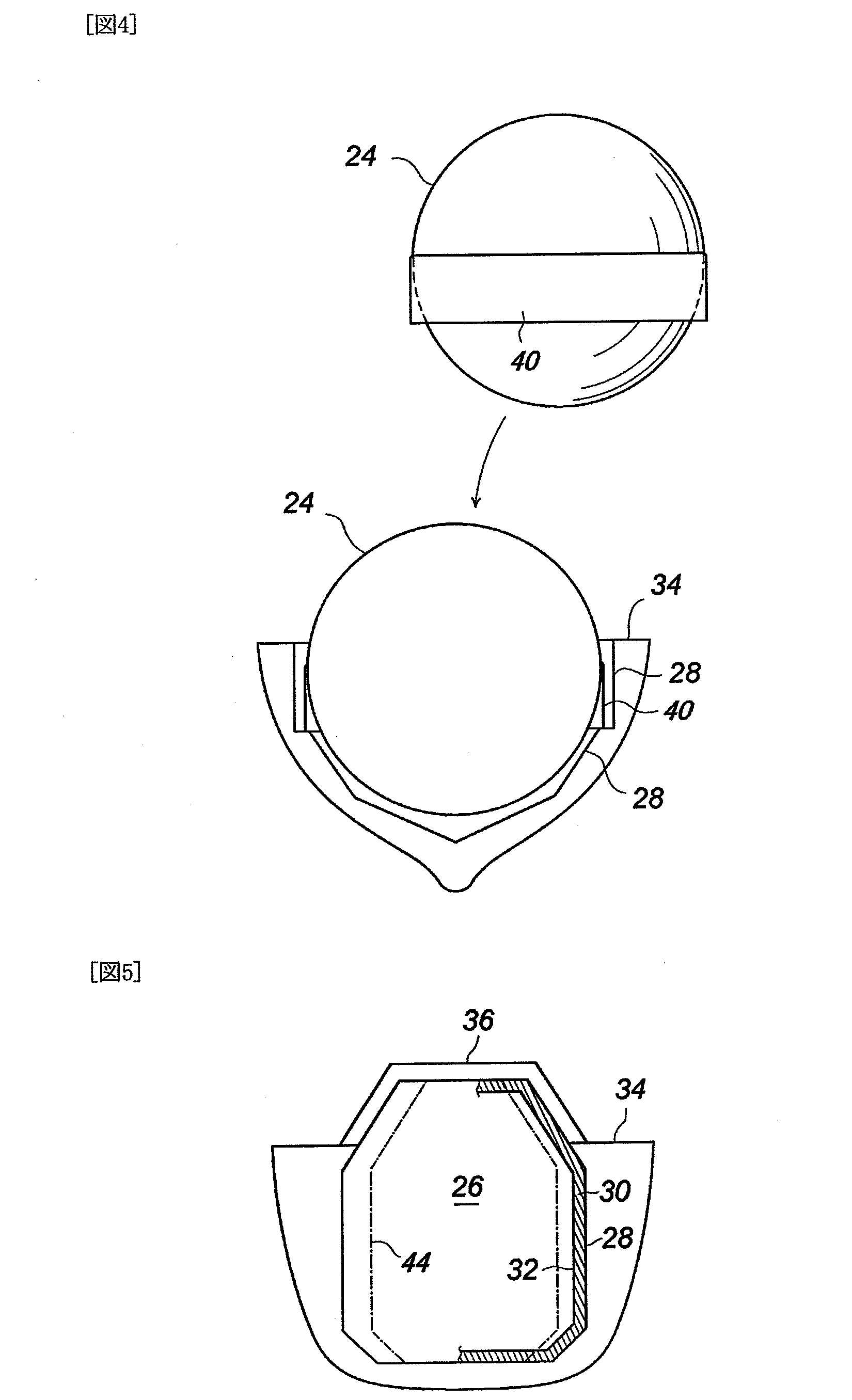
[0022]FIG. 4 shows a transverse sectional view of the foremost division in which the sphe...


PUM


Abstract

An LNG tanker is provided which can have larger tank capacity for its hull size, be easily built, and reduce the sloshing in membrane type tanks during a heavy weather. The foremost LNG tank is made in a spherical independent type (24), and each of subsequent tanks is made in membrane type (26). The membrane type of tank has heat insulating material on the inner shell of a double hull with its surface covered by membranes. During the voyage, the liquid cargo (LNG) in the spherical independent type tank is transferred to membrane type of tanks, thereby to compensate LNG losses caused by generation of boil-off gas in the membrane type tanks.

Description

TECHNICAL FIELD [0001]The present invention relates to marine transportation of liquefied natural gas (LNG).BACKGROUND ART [0002]There is an increasing demand for LNG as clean energy, since LNG emits less nitrogen oxide and sulfur dioxide during burning. LNG can be produced by cooling the natural gas down to approximately −160° C. where it turns into a liquid. A tanker for marine-transporting LNG is provided with cargo tanks which are made of cryogenic materials to withstand extremely low temperature, and have structures to provide for thermal detonation of materials due to temperature differences. Further, most of LNG tankers can sail at sea speed of about 20 knots in order to undertake a role of high-speed and mass transportation. In recent years LNG tankers are getting larger, and there are plans to construct LNG tankers with tank capacity of more than 200,000 m3.[0003]In LNG tankers of the prior art, LNG tanks thereon are roughly divided into two types; one is of the spherical f...

Claims


Application Information

Patent Timeline
Patent Type & Authority Applications(United States)
IPC IPC(8): B63B25/16B63B25/12
CPCB63B25/16F17C2221/033F17C2223/0161F17C2260/016F17C2270/0105B65D90/52F17C3/027B63B2025/087F17C2270/0107
Inventor MORIMOTO, NOBUYOSHI
Owner MORIMOTO
Why Eureka
Try Eureka