
Airborne tunable mid-ir laser gas-correlation sensor

a technology of laser gas correlation and airborne tunable, applied in the direction of optical radiation measurement, instruments, and reradiation, can solve the problems of difficult to quantify the gas concentration in real time, the conventional laser system is not suitable, and the use of blackbody sources is not practical in many applications

Inactive Publication Date: 2010-07-01
SCI & ENG SERVICES
View PDF12 Cites 17 Cited by
  • Summary
  • Abstract
  • Description
  • Claims
  • Application Information

AI Technical Summary

Benefits of technology

The present invention provides a method and apparatus for measuring target gas concentrations in an atmosphere. The method involves emitting a laser beam tuned to a molecular absorption line of a target gas, and receiving a reflected signal affected by gas absorption of the target gas. The received signal is then divided and directed into two optical paths, and transmitted signals are detected through both paths. The target gas concentration is calculated by comparing a first signal transmitted through the first optical path to a second signal transmitted through the second optical path. The technical effect of this invention is to provide a more accurate and reliable method for measuring target gas concentrations in an atmosphere.

Problems solved by technology

While a conventional laser system may have enough brightness to be used, if it can be tuned to the desired infrared range, a conventional laser system is not suitable due to the narrow spectral line features of the laser radiation.
Also changes in the surface reflectivity and inhomogeneity in the background can give rise to serious errors with the passive technique and make it difficult to quantify the gas concentration in real time.
A high temperature blackbody source can be used as an active illumination source, but utilization of a blackbody source is not practical in many applications.

Method used


Image

  • Airborne tunable mid-ir laser gas-correlation sensor
  • Airborne tunable mid-ir laser gas-correlation sensor
  • Airborne tunable mid-ir laser gas-correlation sensor

Examples


Embodiment Construction

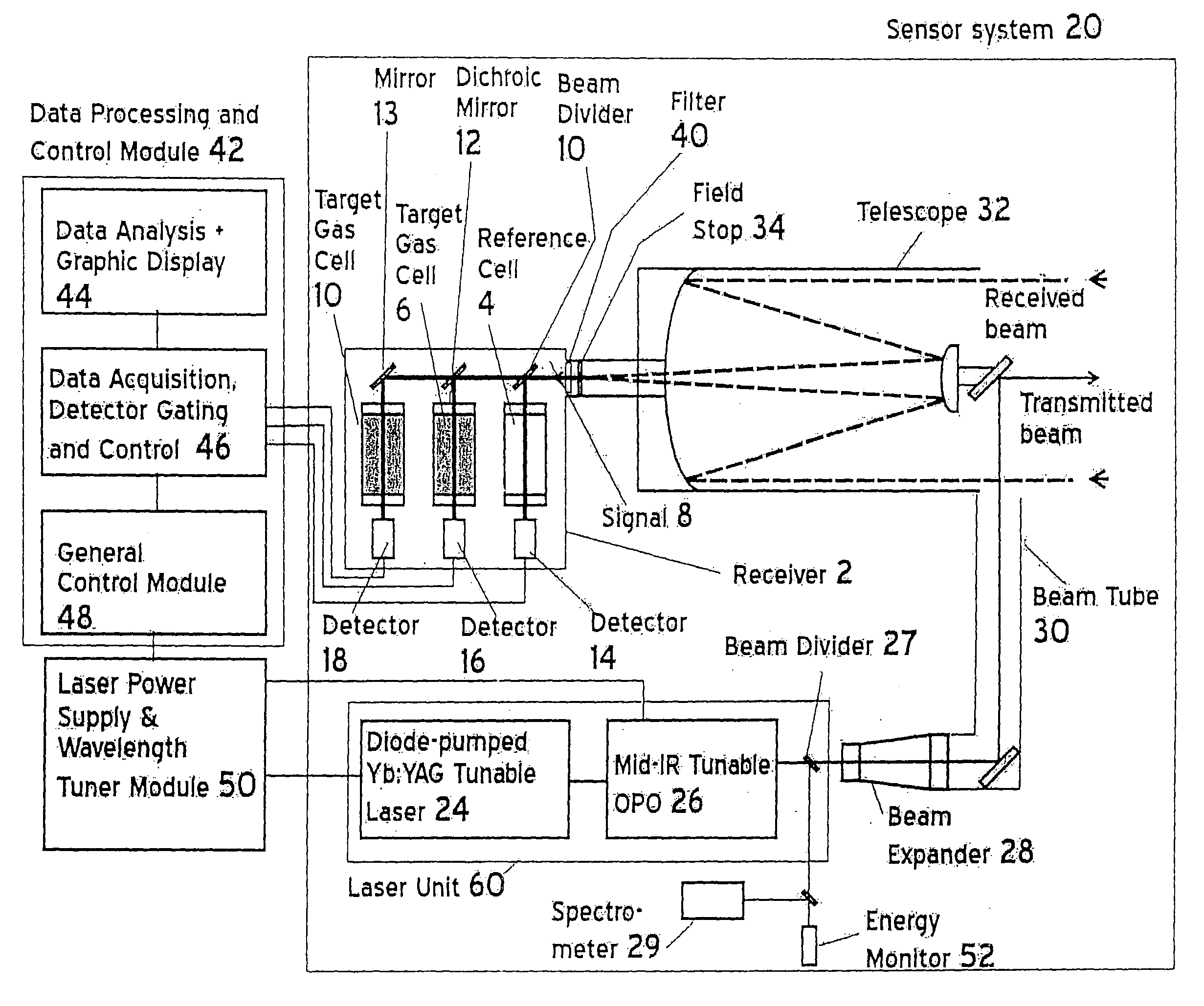
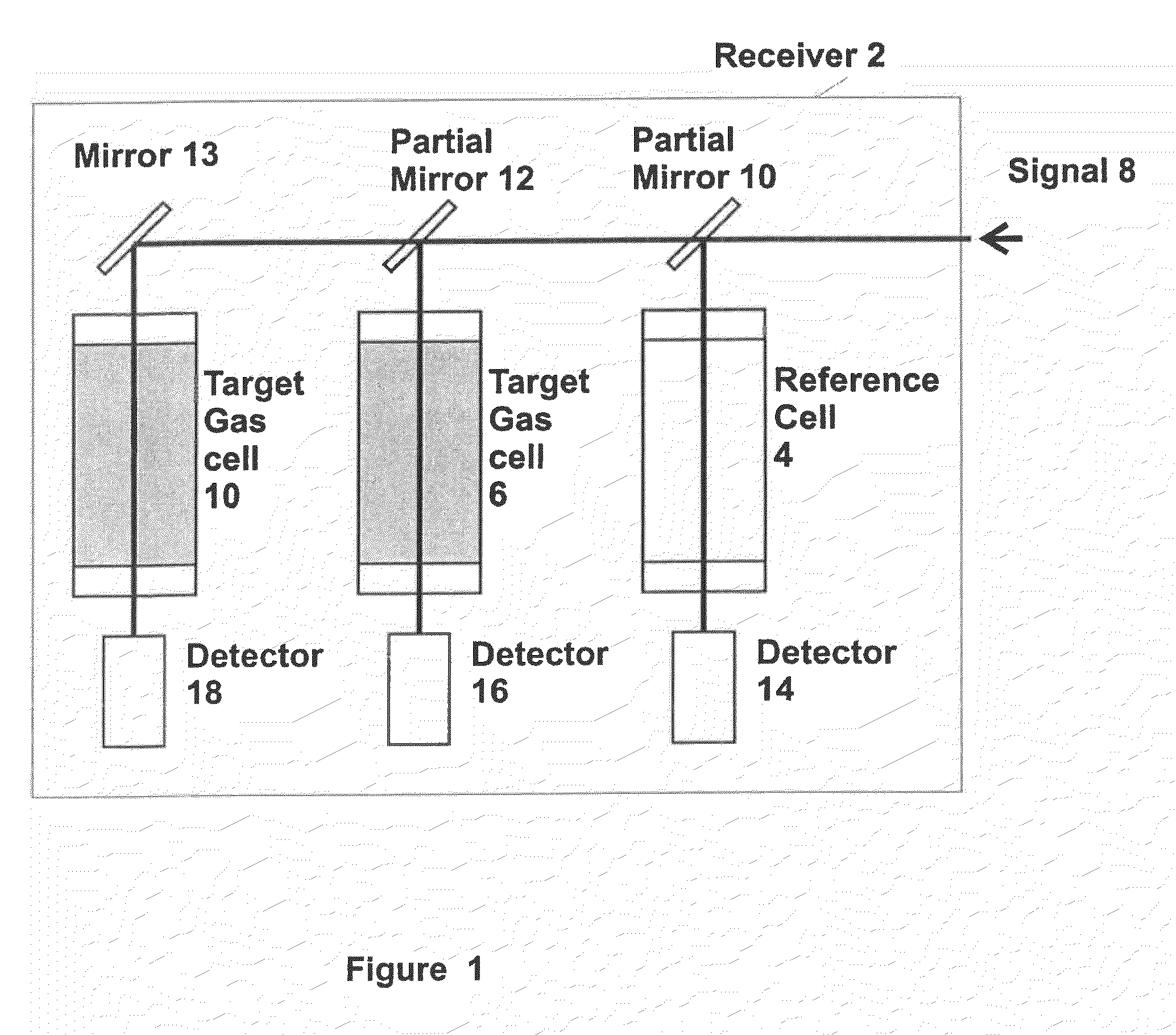
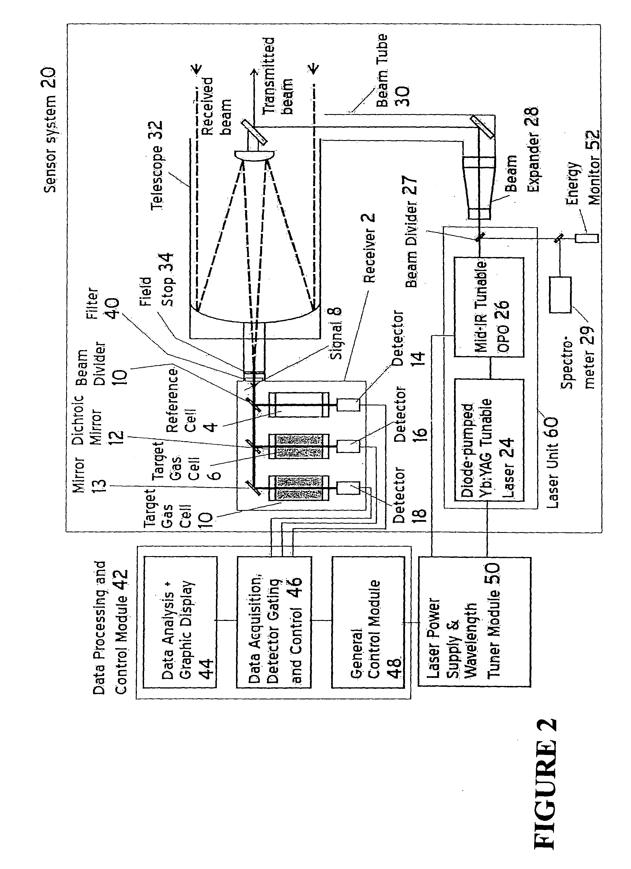
[0034]Referring now to the drawings, wherein like reference numerals designate identical, or corresponding parts throughout the several views, FIG. 1 is a schematic representation of a laser gas correlation sensor receiver 2 according to a non-limiting embodiment of the present invention. As shown in FIG. 1, incoming radiation signal 8 which is affected by the target gas outside the sensor system, is divided into two or more paths. One path is directed to a correlation gas channel (or the “on” line channel), and another path is directed to a reference gas channel (or the “off” line channel). As shown illustratively in FIG. 1, the sensor receiver 2 includes a reference cell 4 (i.e., the “off” line channel) filled with a non-target gas having spectrally inert characteristics such as for example air. The sensor receiver 2 includes a target gas cell 6 (i.e., the “on” line channel) filled with a target gas providing a known absorbance over a known optical distance (i.e., the interior dis...


PUM

PropertyMeasurementUnit
mid-IR wavelength rangeaaaaaaaaaa
output energyaaaaaaaaaa
widthaaaaaaaaaa

Abstract

A method and apparatus for measuring target gas concentrations in an atmosphere. The method and apparatus emit in the atmosphere a laser beam tuned to a molecular absorption line of a target gas, receive a reflected signal affected by gas absorption of the target gas in the atmosphere, divide and direct the received signal into a first optical path and a second optical path including in one of the paths a correlation gas cell filled with a predetermined concentration of the target gas, detect transmitted signals through the first optical path and the second optical path, and calculate a target gas concentration by comparing a first signal transmitted through the first optical path to a second signal transmitted through the second optical path. The apparatus includes a laser source tunable to a specific molecular absorption line of a target gas and configured to emit in the atmosphere a laser beam having a spectral bandwidth greater than a full width of the molecular absorption line of the target gas, a receiver configured to receive a reflected signal affected by gas absorption of the target gas in the atmosphere, and at least one detector configured to detect transmitted signals through the first optical path and the second optical path.

Description

CROSS-REFERENCE TO RELATED APPLICATIONS[0001]This application is a Divisional of and claims the benefit of priority under 35 U.S.C. §120 from U.S. Ser. No. 11 / 737,547, filed Apr. 19, 2007, the entire contents of which are incorporated herein by reference.DISCUSSION OF THE BACKGROUND[0002]1. Field of the Invention[0003]The invention relates to a sensor and method for detecting natural gas in the atmosphere.[0004]2. Background of the Invention[0005]Gas correlation is known to be one of the more sensitive optical measurement techniques which uses infrared emission from or absorption of a gas of interest to estimate the concentration of that gas in the sensing environment. The principle of measurement is based on a spectral correlation between a target gas of interest and a correlation gas normally the same as the target gas and contained in a cell inside the sensor. In a typical application, the correlation cell is filled with the target gas of interest to a specific pressure (i.e., co...

Claims


Application Information

Patent Timeline
Patent Type & Authority Applications(United States)
IPC IPC(8): G01N21/61G01N21/84
CPCG01N21/3518Y02A90/19G01S17/95G01N21/39Y02A90/10G01N2021/1795G01N2021/3513
Inventor PRASAD, COORG RANGASWAMYLIN, BOLEE, HYO SANG
Owner SCI & ENG SERVICES
Learn More