

Mid-infrared parameter oscillator
An optical parametric oscillator and parametric oscillator technology, applied in the laser field, can solve problems such as the difficulty in obtaining high-power mid-infrared lasers, the increase in the complexity and volume of lasers, and the increase in the magnification of compressed telescopes, achieving cost-effectiveness, simple structure, low cost effect
- Summary
- Abstract
- Description
- Claims
- Application Information
AI Technical Summary
Problems solved by technology
Method used
Image

Examples
Embodiment 1
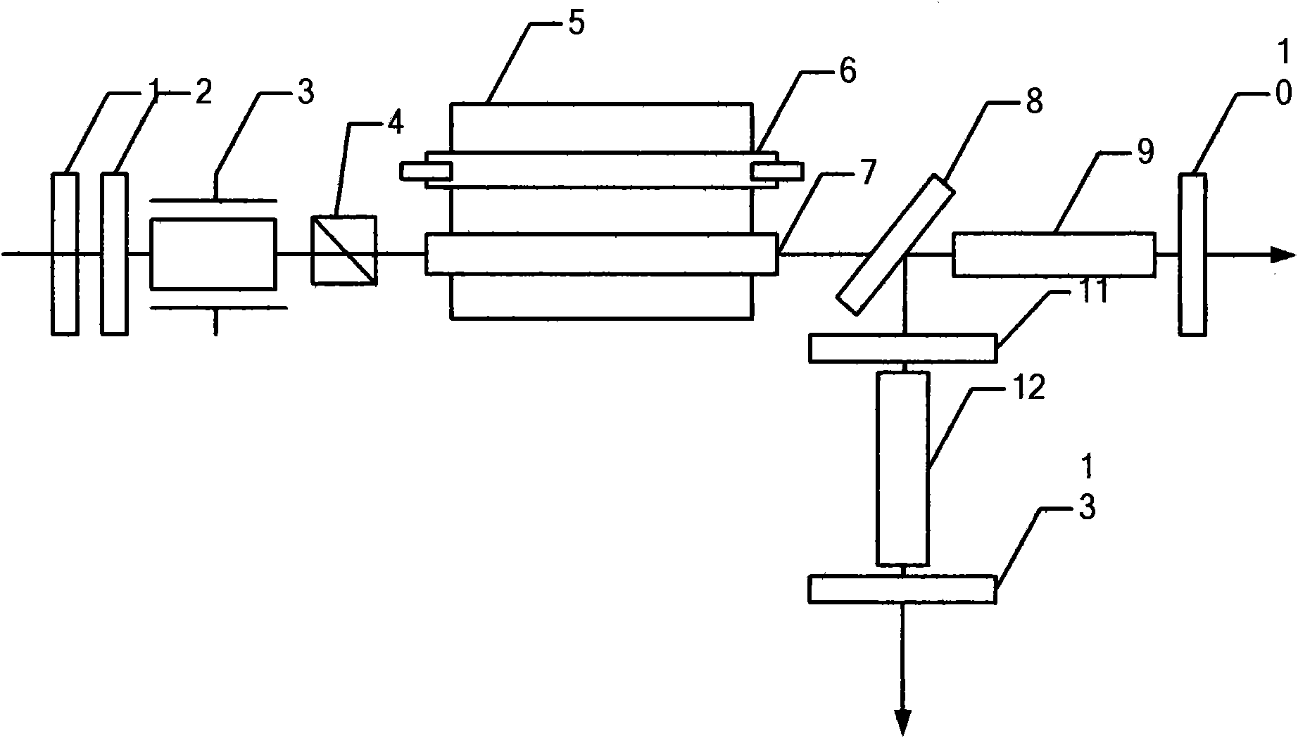
[0026] Such as figure 1 Shown: a kind of mid-infrared optical parametric oscillator, it has a 1.06 μm laser, two-stage optical parametric oscillator and light collecting cavity 5; The first-stage output cavity mirror 10, the first-stage optical parametric oscillator and the second-stage optical parametric oscillator share the second-stage output cavity mirror 13; a xenon lamp 6 and a laser crystal 7 are installed in the focusing cavity 5 . The first-stage optical parametric oscillator is a 1.06 μm pumped intracavity non-critical phase-matched KTA optical parametric oscillator, and the second-stage optical parametric oscillator is a 1.53 μm pumped intracavity non-critical phase-matched KTA optical parametric oscillator. The 1.06 μm laser is a Q-switched laser, and its laser resonator includes a 1.06 μm total anti-cavity mirror 1, a first-stage optical parametric oscillator output cavity mirror 10, and a Q-switching component; the Q-switching component is an electro-optic Q-swit...
Embodiment 2
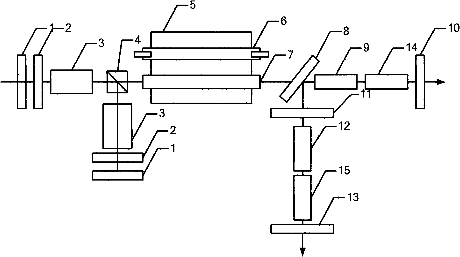
[0028] Such as figure 2 As shown, the difference from the above-mentioned embodiment 1 is that the Q-switching component of the 1.06 μm laser is composed of two sets of electro-optic crystals 3, a 1 / 4 wave plate 2 and a polarization element 4; that is, the polarization element 4 has two polarization paths , each polarized optical path has a total reflection cavity mirror 1, an electro-optic crystal 3 and a wave plate 2, and the two paths of light are synthesized by the total reflection cavity mirror 1 in the polarization element 4 and propagated to the right as unpolarized light; the first-order optical parameter The oscillator is added with the first-level KTA crystal 14, which has the same cutting angle and coating as the first-level first KTA crystal 9, and its y-axis direction is consistent with another polarization direction of the polarizing element 4; The second-level optical parametric oscillator is added with the second-level KTA crystal 15, which has the same cuttin...
Embodiment 3
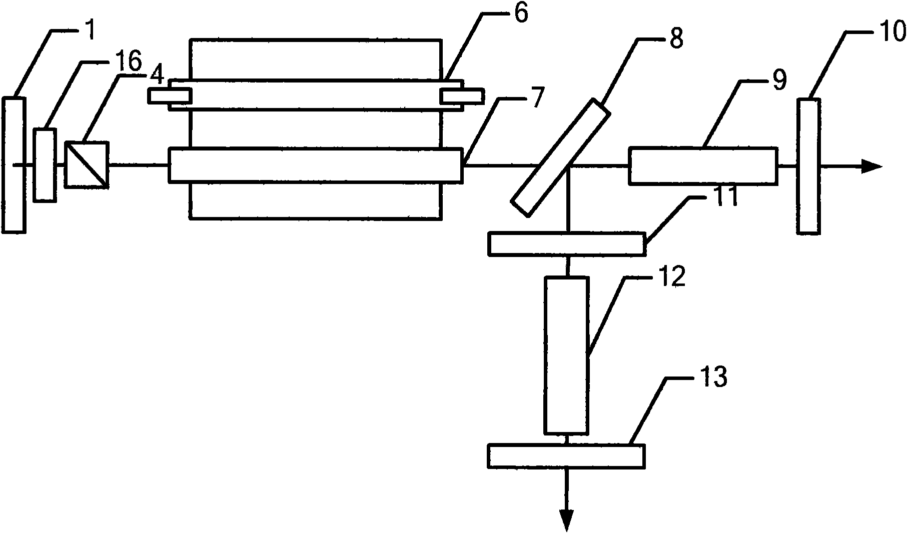
[0030] Such as image 3 As shown, the difference from the above-mentioned embodiment 1 is that the 1.06 μm laser is a 1.06 μm passive Q-switched laser or an acousto-optic Q-switched laser, and there is a polarization element 4 in the 1.06 μm resonant cavity, a passive Q-switched component or an acousto-optic Q-switched laser. The components are in different positions in the 1.06 μm laser resonator, such as passive Q-switching components or acousto-optic Q-switching components 16 between the polarization component 4 and the laser crystal 7, or between the full-reverse cavity mirror 1 and the polarization component 4, or Between the laser crystal 7 and the pump light input mirror 8 .
PUM
 Abstract
Description
Claims
Application Information