
Down-converter mixer

a converter mixer and converter technology, applied in the field of down-converter mixers, can solve the problems of not achieving satisfactory results, requiring a very high capacitance value, and three above-mentioned approaches are far from optimal, so as to achieve efficient reduction of low frequency noise currents, increase the output impedance of tail generators, and high impedance

Inactive Publication Date: 2010-07-01
STMICROELECTRONICS SRL
View PDF4 Cites 12 Cited by
  • Summary
  • Abstract
  • Description
  • Claims
  • Application Information

AI Technical Summary

Benefits of technology

The patent text describes an approach to reducing noise in a mixer by using a down-converter mixer with specific characteristics. The approach involves increasing the output impedance of the tail generators to reduce low-frequency noise currents. The mixer operates by allowing a common source node to be mildly discharged during the zero-crossings of the local oscillator signal. The inventor observed that previous approaches, such as using feedback or antagonist circuits, did not provide optimal results. The new approach overcomes these drawbacks by using a high impedance around the frequency of the LO signal and an open-loop mechanism. The technical effect of the approach is to efficiently reduce noise in the mixer without the need for external filters.

Problems solved by technology

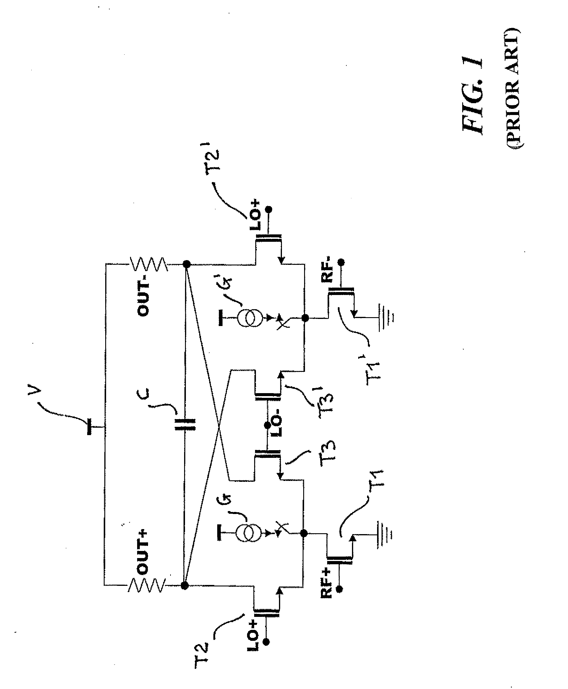
The inventor observed that approaches like the one illustrated in FIG. 1, generally suitable to allow a reduction of the noise figure (NF) even in the order of 6 dB, for particular dimensioning do not allow satisfactory results to be attained.
Regarding the IIP2 issues, the inventor observed, for example, that the three above-mentioned approaches are far from optimal.
Apart from being suboptimal from the noise point of view, this approach generally requires a very high capacitive value, such to complicate implementation thereof.

Method used


Image

  • Down-converter mixer
  • Down-converter mixer
  • Down-converter mixer

Examples


Embodiment Construction

[0029]Illustrated in the following description are various specific details aimed at an in-depth understanding of the embodiments. The embodiments may be obtained without one or more specific details, or through other methods, components, materials, etc. In other cases, known structures, materials or operations are not shown or described in detail to avoid obscuring the various aspects of the embodiments. Reference to “an embodiment” in this description indicates that a particular configuration, structure or characteristic described regarding the embodiment is included in at least one embodiment. Hence, expressions such as “in an embodiment”, possibly present in various parts of this description do not necessarily refer to the same embodiment. Furthermore, particular configurations, structures or characteristics may be combined in any suitable manner in one or more embodiments.

[0030]References herein are used for facilitating the reader and thus they do not define the scope of prote...


PUM


Abstract

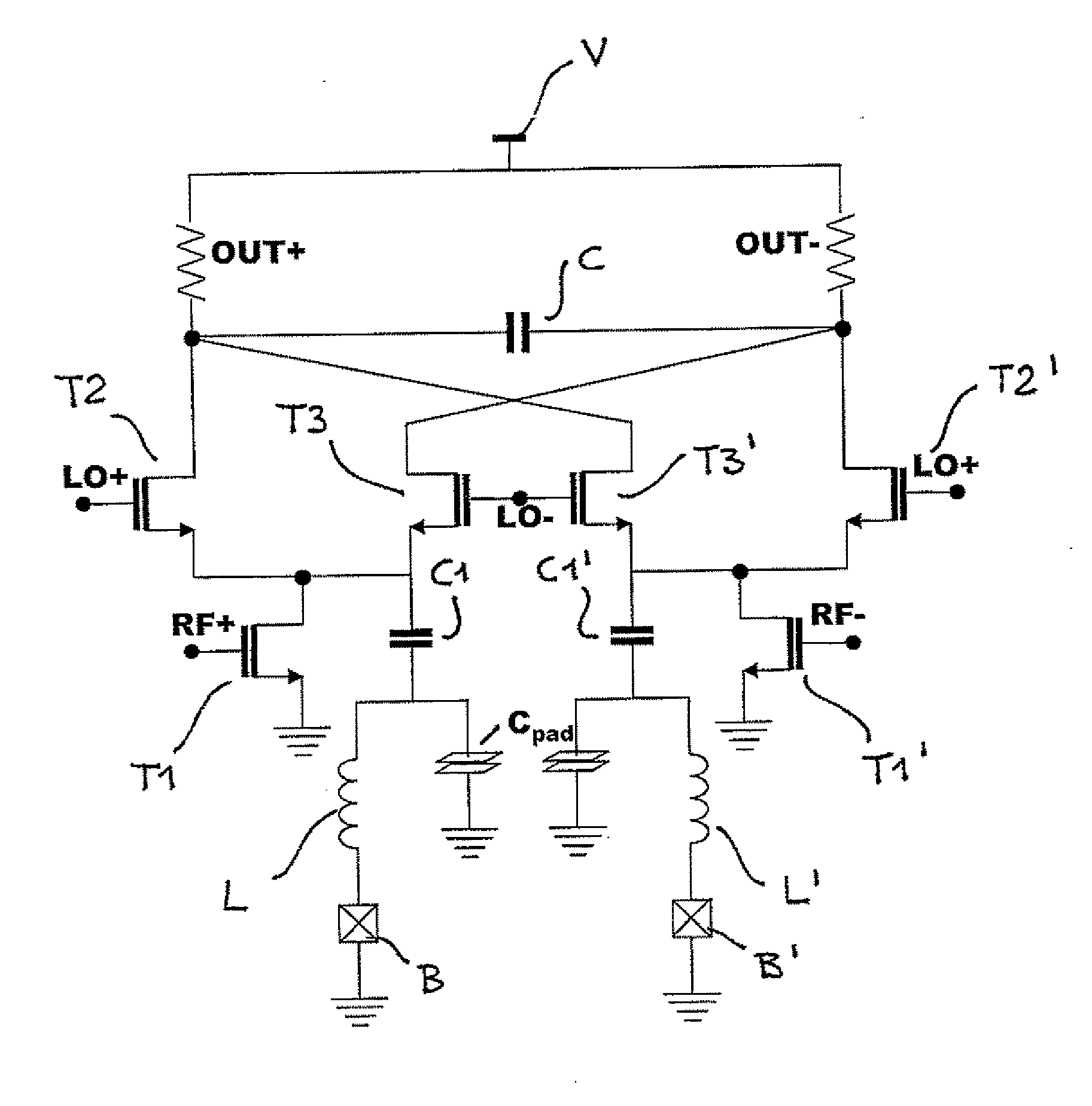
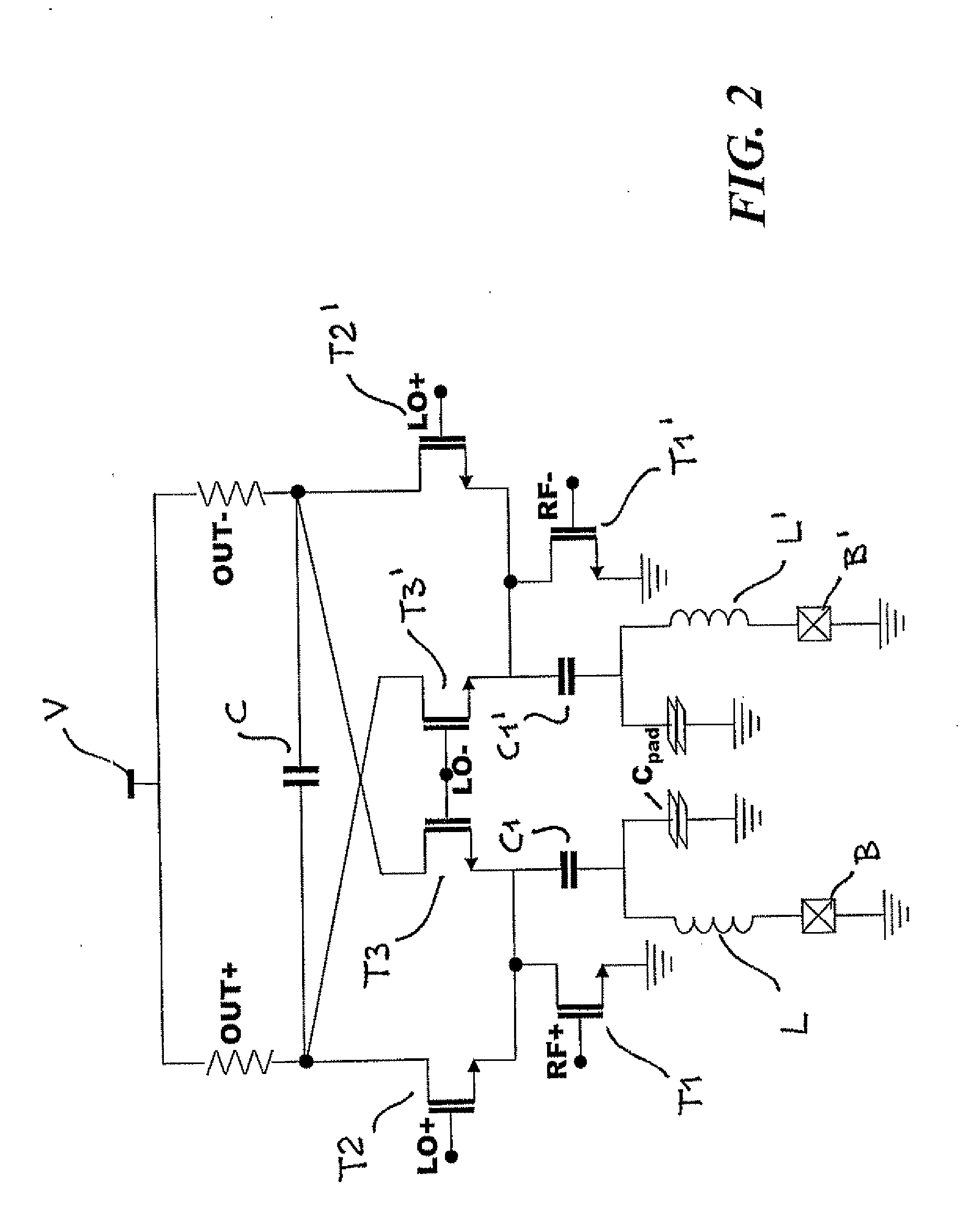
A down-converter mixer may include a Gilbert cell, two transistor differential pairs, which drive output loads, and transistors defining respective tail generators coupled to common source nodes of the differential pairs. The transistors may receive a radio-frequency signal mixable with a local oscillator signal applied symmetrically between the differential pairs to produce in the loads, a signal deriving from down-converting the radio-frequency signal of an amount given by the frequency of the local oscillator signal. An inductor may be coupled to the common source nodes and which resonates with a capacitive load also coupled to the common source nodes, increases the impedance of such common nodes at the local oscillator signal frequency. The inductor may be in an open loop configuration in the absence of feedback from the mixer, and thus may be active both against noise at radio-frequency and distortion at low frequency.

Description

FIELD OF THE INVENTION[0001]The present description refers to down-converter mixers. The description was developed with particular attention to the possible application to down-converter mixers of the active type.BACKGROUND OF THE INVENTION[0002]Down-converter mixers, in particular of the active type, represent an important component in numerous receivers of the wireless type. As a matter of fact, such mixers allow performing a mixing operation accompanied by a gain (for example, a voltage gain) such to make the conditions required to be met by the receiver front-end low-noise amplifier less strict.[0003]Thus, down-converter mixers of the active type improve the performance of the receiver in that they introduce a gain in the frequency conversion operation. Furthermore, while superheterodyne receivers generally require external filters for image rejection, the direct conversion architecture (or with null intermediate frequency, i.e., zero-IF) is suitable for a fully integrated imple...

Claims


Application Information

Patent Timeline
Patent Type & Authority Applications(United States)
IPC IPC(8): H03D7/12
CPCH03D7/1433H03D7/1441H03D7/1458H03D7/1491
Inventor RADICE, FRANCESCO
Owner STMICROELECTRONICS SRL
Learn More