SOFC Cathode and Method for Cofired Cells and Stacks

a cofired cell and stack technology, applied in the field of cofired cell and stack cofired cathode and method, can solve the problems of easy damage to the fabrication of fuel cells and stacks, and achieve the effects of eliminating the requirement of air permeability, simplifying co-fireing, and great flexibility

Inactive Publication Date: 2010-07-01
SAINT GOBAIN CERAMICS & PLASTICS INC
View PDF17 Cites 13 Cited by
  • Summary
  • Abstract
  • Description
  • Claims
  • Application Information

AI Technical Summary

Benefits of technology

[0009]This invention has many advantages. For example, separate fabrication of anode / electrolyte and cathode / interconnect subcomponents provides for greater flexibility in conditions under which the components are assembled to form the fuel cell. In one embodiment, separate fabrication of the anode / electrolyte and cathode / interconnect subcomponents can be conducted at higher temperatures, followed by assembly of fuel cell components by insertion of a porous, cathode functional layer between the cathode layer of one subcomponent and the electrolyte layer of the other subcomponent, and subsequent firing of the assembly at a temperature significantly below that required to optimally prepare the anode / electrolyte and cathode / interconnect subcomponents. Other fuel cell components can be included in each subassembly by this technique, whereby lower temperatures are employed during assembly of the components than are required to produce respective subcomponents. Examples of such other subcomponents include nonfunctional anode layers and bonding components, such as compositions that include nickel mesh, which can be employed to link assemblies of fuel cells previously linked in series. Also, fabrication techniques and materials that constitute the cathode layer can be optimized by fabricating a cathode bulk layer in combination with an interconnect layer prior to incorporation of a porous active functional cathode layer during assembly of a fuel cell. Moreover, a subcomponent cathode layer can include air channels at an interface between cathode bulk and cathode functional layers, thereby eliminating the requirement of air permeability through the cathode bulk, and simplifying co-firing of the cathode bulk layer adjacent the interconnect layer of each fuel cell component of a fuel cell assembly. In addition, cathode bulk layers generally provide greater mechanical support at interconnect layers than do porous counterparts. Further, additional fabrication techniques can be employed, such as molding or machining channel structures into a portion of a cathode bulk layer distal to the interface with an interconnect layer, prior to combination with a porous green body that will be co-fired with the bulk cathode / interconnect and anode / electrolyte subcomponents to form a fuel cell component of a fuel cell assembly.
[0010]The present invention can be used in a solid oxide fuel cell (SOFC) system. SOFCs offer the potential of high efficiency electricity generation, with low emissions and low noise operation. They are also seen as offering a favorable combination of electrical efficiency, co-generation heat efficiency and fuel processing simplicity. One example of a use for SOFCs is in a home or other building. The SOFC can use the same fuel that is used to heat the home, such as natural gas. The SOFC system can run for extended periods of time to generate electricity to power the home and if excess amounts are generated, the excess can be sold to the electric grid. Also, the heat generated in the SOFC system can be used to provide hot water for the home. SOFCs can be particularly useful in areas where electric service is unreliable or non-existent.

Problems solved by technology

However, fabrication of fuel cells and stacks can be susceptible to damage caused by a fluctuation in temperature.
All of these problems are compounded by assembling fuel cell subunits in stacks which must be co-fired during production, and by extended use of stacked assemblies which may be exposed to repetitive and dramatic changes in temperatures during normal operation.

Method used


Image

  • SOFC Cathode and Method for Cofired Cells and Stacks
  • SOFC Cathode and Method for Cofired Cells and Stacks
  • SOFC Cathode and Method for Cofired Cells and Stacks

Examples


second embodiment

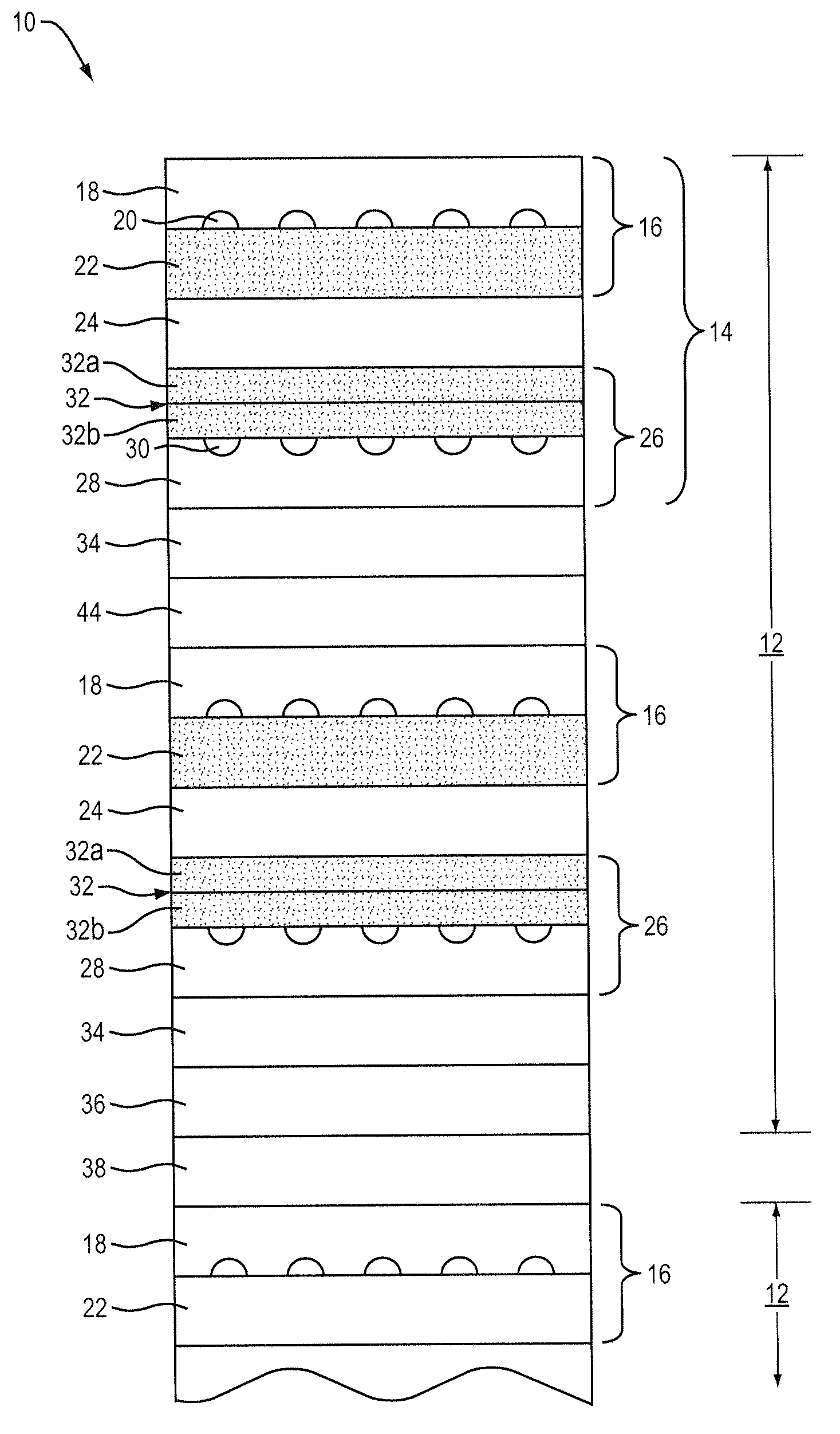
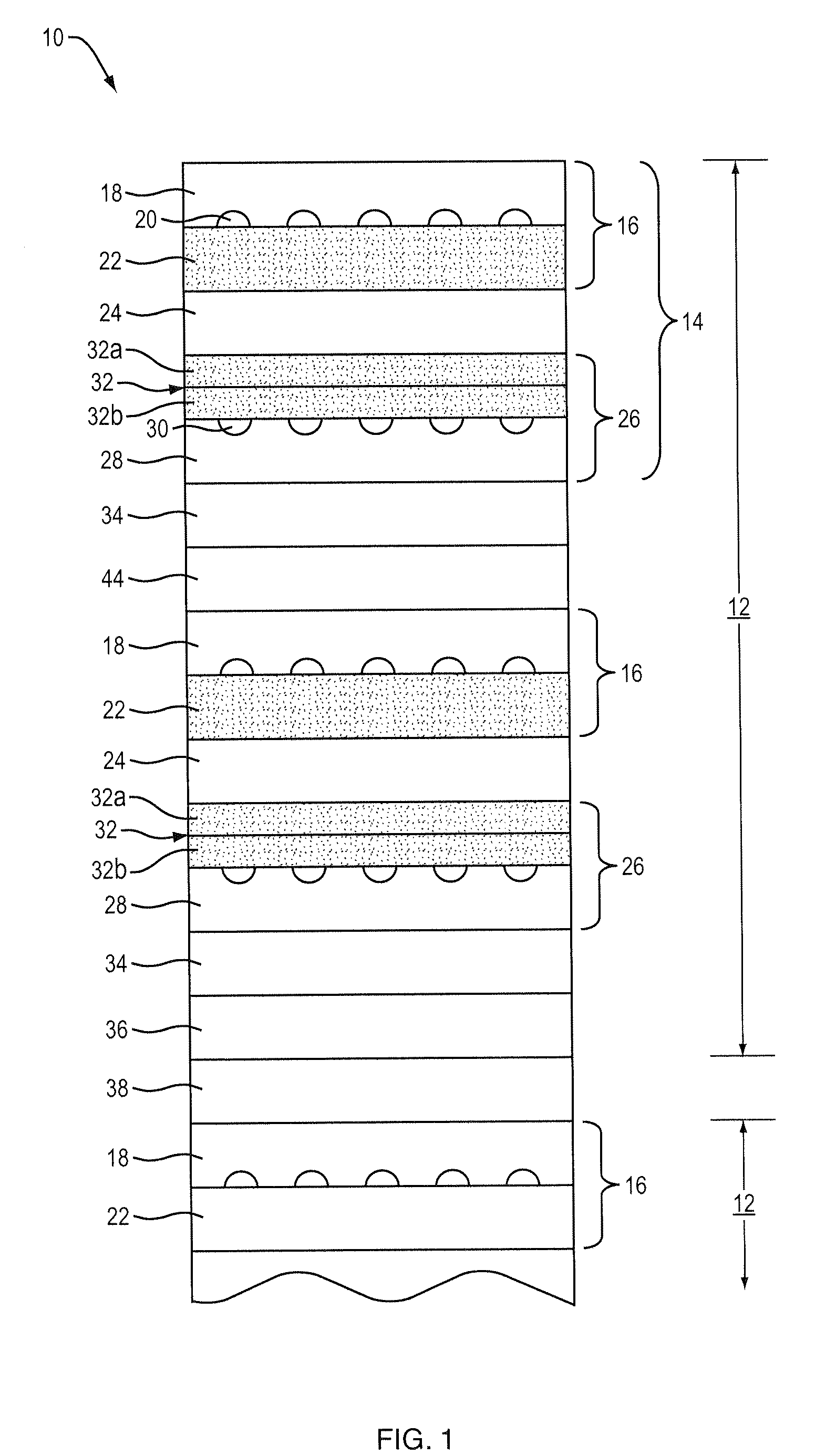
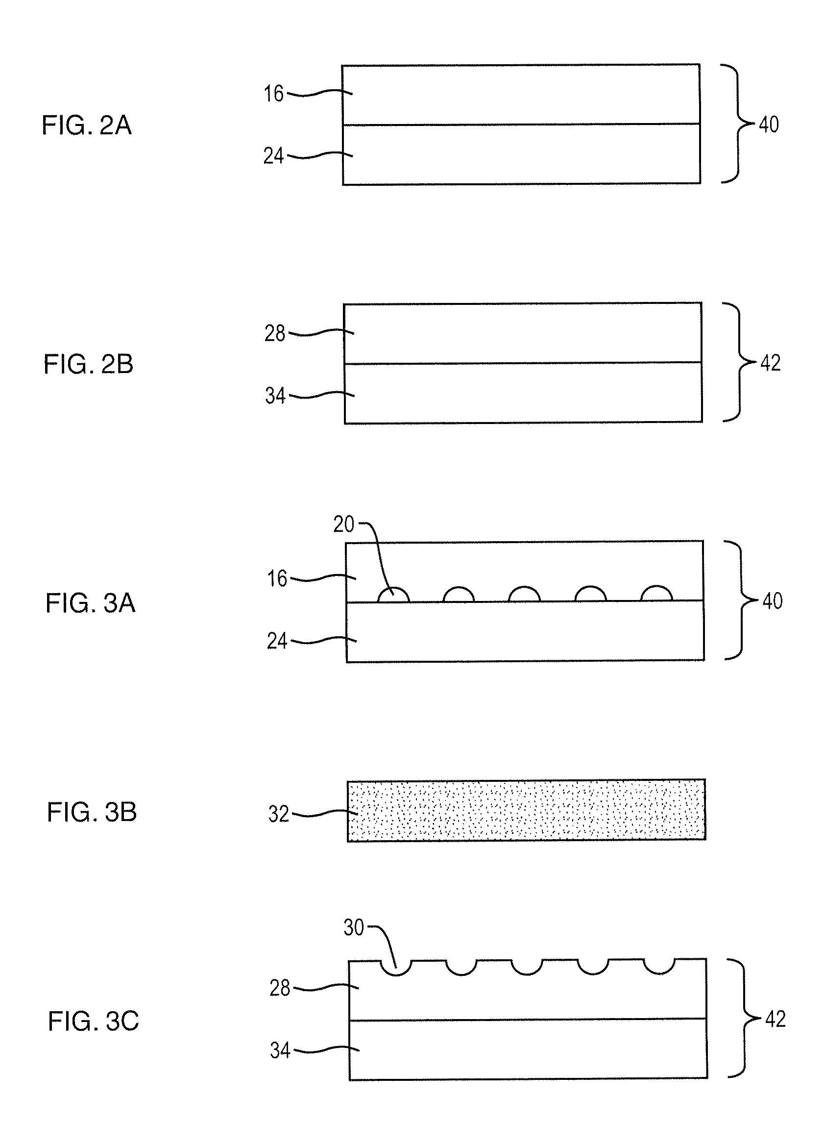
[0038]In a second embodiment, a plurality of anode subcomponents 40, cathode subcomponents 42 and green functional cathode layers 32 are co-fired at a suitable temperature, preferably lower than that employed to form each of the anode subcomponents 40 and cathode subcomponents 42, to thereby form fired subcells. The fired subcells 14 are then arranged together with conformable anode bond layer 44 and compressed into a fuel cell stack 8. An example of a suitable conformable bonding layer is a bonding layer that includes nickel mesh or nickel felt preferably coated with nickel paste.

third embodiment

[0039]In a third embodiment, a plurality of anode subcomponents 40, cathode subcomponents 42 that contain a terminal anode, green functional cathode layers 32 and green anode bond layer 44 can be arranged and co-fired at a suitable temperature, preferably lower than that employed to form each of the anode subcomponents 40 and cathode subcomponents 42, to thereby form a fuel cell stack 8. An example of a suitable anode bond layer is a layer consisting of Ni metal with YSZ ceramic or Ni with YSZ and interconnect ceramic material.

fourth embodiment

[0040]In a fourth embodiment, a plurality of anode subcomponents 40, cathode subcomponents 42 that contain a terminal anode and green functional cathode layers 32 are co-fired at a suitable temperature, preferably lower than that employed to form each of the anode subcomponents 40 and cathode subcomponents 42, to thereby form fired subcells. The fired subcells 14 are then arranged together with conformable anode bond layer 44 and compressed into a fuel cell stack 8. An example of a suitable conformable bonding layer is a bonding layer that includes nickel mesh or nickel felt preferably coated with Ni paste.


PUM

PropertyMeasurementUnit
particle sizeaaaaaaaaaa
grain sizeaaaaaaaaaa
molar ratioaaaaaaaaaa

Abstract

A solid oxide fuel cell includes an anode layer, an electrolyte layer over a surface of the anode layer, and a cathode layer over a surface of the electrolyte layer. The cathode layer includes a cathode bulk layer, a porous cathode functional layer at an electrolyte, an intermediate cathode layer partitioning the cathode bulk layer and the porous cathode functional layer, the porous intermediate cathode layer having a porosity greater than that of the cathode bulk layer. The solid oxide fuel cells can be combined to form subassemblies that are bonded together to form solid oxide fuel cell assemblies.

Description

RELATED APPLICATION[0001]This application claims the benefit of U.S. Provisional Application No. 61 / 204,034, filed on Dec. 31, 2008. The entire teachings of the above application are incorporated herein by reference.BACKGROUND OF THE INVENTION[0002]Fuel cells generate electricity by a chemical reaction wherein oxygen gas is reduced to oxygen ions (O2−) at a cathode, and a fuel gas, such as H2 gas, is oxidized with the oxygen ions to form water at an anode. Solid oxide fuel cells employ a hard, ceramic compound metal (e.g., calcium or zirconium) oxide as an electrolyte between a functioning cathode and a functioning anode.[0003]In some embodiments, fuel cells are arranged in stacks, whereby subassemblies, each including a cathode, an anode and a solid electrolyte between the cathode and anode, are assembled in series by locating an electrical interconnect between the cathode of one subassembly and the anode of another. However, fabrication of fuel cells and stacks can be susceptible ...

Claims


Application Information

Patent Timeline
Patent Type & Authority Applications(United States)
IPC IPC(8): H01M8/10H01M8/00
CPCH01M4/9033H01M8/1213H01M8/1246H01M8/2465Y02E60/521Y10T29/49108H01M8/124H01M8/2425H01M4/8652H01M4/8889H01M8/1226Y02E60/525H01M8/2432Y02E60/50Y02P70/50H01M8/02H01M8/12H01M8/24
Inventor REILLY, CHRISTOPHER J.LIN, GUANGYONGNARENDAR, YESHWANTH
Owner SAINT GOBAIN CERAMICS & PLASTICS INC
Why Eureka
Try Eureka