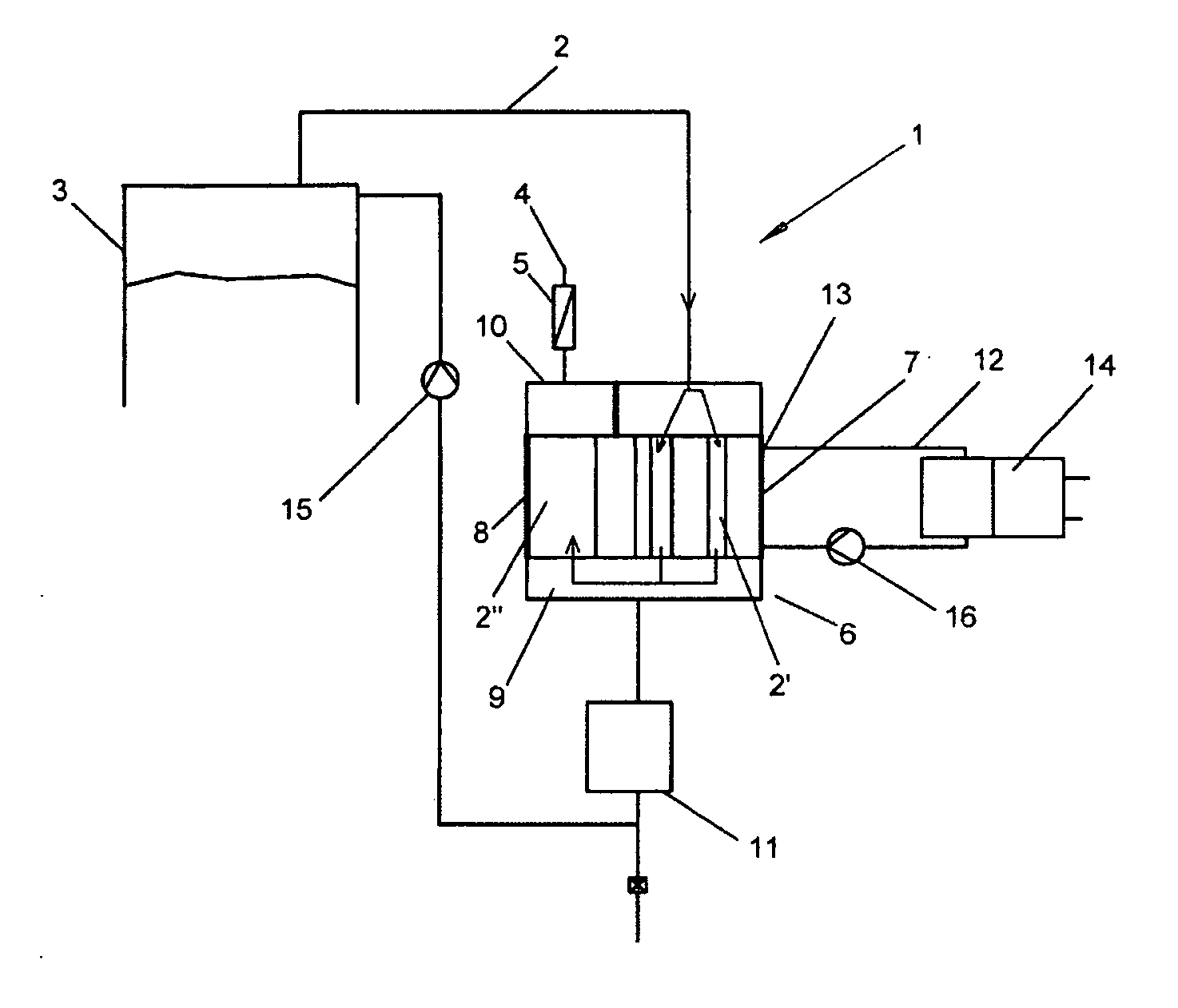
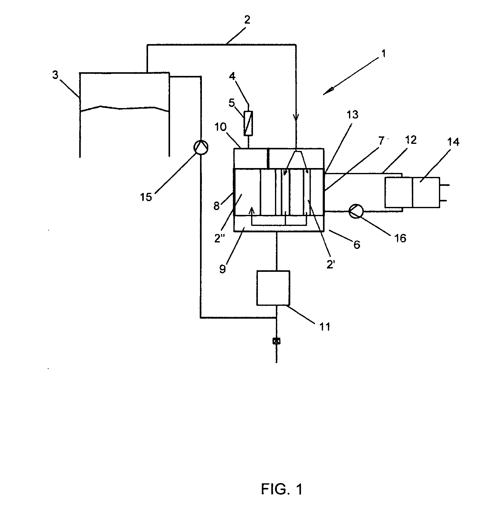
[0009]The object is achieved by way of a waste gas system for bioreactors, at least comprising at least one gas outflow duct for discharging waste gas from a bioreactor vessel, wherein a hydrophobic sterile filter is arranged upstream of the opening of the at least one gas outflow duct toward the surroundings with a heat exchanger located upstream thereof. Here, the at least one gas outflow duct is divided in at least one cooling zone of the heat exchanger into a multiplicity of subducts, and the at least one gas outflow duct is extended in at least one heating zone of the heat exchanger to a calming zone for the waste gas. Due to the division of the gas outflow duct into a multiplicity of subducts in the cooling zone of the heat exchanger, a considerably larger surface area for the removal of heat from the waste gas via the subducts is available, with the result that even in the case of laminar flow of the waste gas through the subducts a
high effectiveness of the separation of liquids from the waste gas can be achieved. In the heating zone, which follows for the waste gas and in which the gas outflow duct extends to a calming zone for the waste gas, the waste gas can heat up again due to the reduced flow rate until it reaches the hydrophobic sterile filter by way of taking up heat from the surroundings to such a degree that the relative vapor contents are below 100% and separation of liquids from residual vapors at or in the hydrophobic sterile filter is precluded. As a result, the hydrophobic sterile filter is reliably protected against becoming blocked by liquids.
[0011]Advantageously, the cooling and the heating zones of the heat exchanger are here connected in a communicating fashion via a base element and, in a preferred embodiment, additionally held together via a head element in order to increase stability. In one preferred embodiment of the invention, the cooling and the heating zones of the heat exchanger are arranged such that they are spaced apart from each other. At least the area of contact between them should be as small as possible. This has the
advantage that between them hardly any heat is transferred and the at least one heating zone can readily absorb heat from the surroundings without being adversely affected by the at least one cooling zone. In one advantageous embodiment of the invention, at least the cooling zones of the heat exchanger are connected in a communicating fashion to a condensate collection vessel, which is arranged underneath it, via the base element. An even more compact design is achieved by designing the base element as part of the condensate collection vessel. This enables the arrangement of the waste gas system for example on the side of or underneath the bioreactor vessel. The space above a bioreactor vessel is frequently needed for fittings, such as supply lines and stirrer connectors. It has also proven expedient if the condensate collection vessel is connected to the bioreactor vessel and / or additionally to the at least one heating zone of the heat exchanger, for example via the base element. As a result, condensate which is entrained into the heating zone can drip into the condensate collection vessel. It is possible for the condensate to be recycled, defined as a function of the
reaction conditions, from the condensate collection vessel into the bioreactor vessel via valves or pumps, in particular metering pumps. In one embodiment of the invention, the pump is preferably designed as a flexible-tube pump (
peristaltic pump). The
advantage is that only the flexible tube has media contact and, after a
single use, can be discarded in
single use systems (disposable systems). The flexible-tube pump, on the other hand, is reusable.
[0012]In a further advantageous embodiment of the invention, the waste gas flows, after the cooling zone, through a condensate separator
package which is integrated for example in the base element of the heat exchanger. This condensate separator
package can be composed of a
highly porous non-woven or of fill bodies (e.g. of Raschig rings) which have a large surface area while at the same time having a very low flow resistance. The non-wovens or fill bodies can, for example, be enclosed in a flexible tube in which the condensate can be received. The flexible tube can be located underneath the base element and connects the cooling zone and the heating zone, with the base element not allowing any direct waste gas flow from the cooling zone into the heating zone. These variants described above lead to a further more compact design of the waste gas system. The condensate separator
package can be connected to the condensate separator vessel or directly to a pump.
[0013]In dependence on the
dew point of the liquid vapors in the waste gas, the multiplicity of subducts is surrounded by a
cooling medium which is appropriately temperature-controlled. The temperature of the
cooling medium should be less than +30° C. Preferred is a range between +10 and −10° C., particularly preferred is a range between +2 and +8° C. In one variant of the invention, at least one Peltier element is introduced for cooling directly into the
cooling medium, preferably in the region of the cooling zone. This variant permits further compacting of the waste gas system. However, an embodiment in which heat can be removed from the cooling medium in a circuit has also proven itself. Thus, the circuit is connected for example to a
heat pump for the removal of the heat. Peltier elements or thermostats can be used as heat pumps. Optimum cooling of the waste gases is achieved when the ratio of the cross section which is free for the waste gases in the multiplicity of subducts to the free cross section for the cooling medium in the cooling zone is in the range of 5:100 to 75:100, preferably in the range of 10:100 to 50:100.
[0015]Particularly advantageous is a waste gas system according to the invention which is made of plastic. Such a waste gas system can be preassembled together with the bioreactor, but at least already sterilized with the bioreactor vessel by the manufacturer and supplied to the user as a sterile single-use unit. The
advantage is of particular importance in bioreactor vessels made of flexible plastics, that is to say when the waste gas system is operable with a bioreactor vessel made of flexible plastic. Such combinations can be reliably sterilized by
irradiation, with the
irradiation preferably being carried out by way of
ionizing irradiation, by way of gamma or
electron rays.



