Unlock instant, AI-driven research and patent intelligence for your innovation.

Aircraft with optimised utility volume and method for optimising the utility volume of an aircraft

a utility volume and aircraft technology, applied in the field of aircraft with effective inner volume, can solve the problems of limited cabin volume, inability to apply to passenger aircraft or cargo aircraft whose fuel is not available immediately, and inability to meet the needs of passengers and cargo aircra

Active Publication Date: 2010-07-08
AIRBUS
View PDF7 Cites 4 Cited by
  • Summary
  • Abstract
  • Description
  • Claims
  • Application Information

AI Technical Summary

Benefits of technology

[0011]The abovementioned objective is reached with an aircraft in which it is possible to access part of the fuel tank when it is not in use, thereby increasing the available usable volume of the aircraft whilst maintaining an identical external structure. This increase in volume can take place during flight when the fuel contained in the tank has been used, thereby improving passenger comfort and available space, or on the ground when the tank is not fully used in order to increase the number of passengers and / or the volume of loaded goods.
[0012]Regarding spacecraft, the invention allows an additional space to be provided for crew, passengers, loads, animals, plants and scientific experiments, whilst using a spacecraft of the same size. Therefore, the weight of the craft is reduced relative to its usable volume, and it therefore consumes less fuel for flying, its manufacturing cost is also lower and less equipment is required compared with a larger-size craft of comparable usable volume.
[0013]Regarding an airplane, if the increase in usable volume is made on the ground, the invention allows the number of passengers or the volume of loaded goods to be increased or, if the increase is made during flight on long-hauls, passenger comfort can be increased.

Problems solved by technology

Cabin volume is limited.
However, this tank is not immediately available as additional living or storage space to store items other than fuel; it needs to be fitted out.
Additionally, this cannot be applied to passenger aircraft or cargo aircraft whose fuel tank is generally contained in the fuselage.
However this modification only applies to cargo volume and not to passenger volume.
Also the increase in available volume cannot be obtained during flight, and the space savings are therefore inoperative on long-hauls.

Method used


Image

  • Aircraft with optimised utility volume and method for optimising the utility volume of an aircraft
  • Aircraft with optimised utility volume and method for optimising the utility volume of an aircraft
  • Aircraft with optimised utility volume and method for optimising the utility volume of an aircraft

Examples


first embodiment

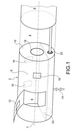
[0063]In FIG. 1, a first embodiment can be seen of an aircraft according to the present invention, comprising a fuselage 2 in which a passenger cabin 4 or passenger compartment is arranged, and at least two fuel tanks 6, 8.

[0064]The first tank 6 will be called the convertible tank and the second tank 8 will be designated a plain tank.

[0065]In this embodiment, the aircraft is an airplane carrying a propulsion system functioning with liquid hydrogen, and more generally an airplane propelled by “clean” fuel. In the present application, by clean fuel or oxidizer is meant a fuel or oxidizer which leaves no trace after its consumption, and which is non-toxic for human beings, such as liquid oxygen, nitrous oxide or liquid hydrogen.

[0066]The propulsion system comprises at least two tanks.

[0067]For an airplane propelled by liquid hydrogen, provision is made to arrange the fuel tanks either side of the passenger cabin 4 in a longitudinal direction X of the fuselage 2. Since this cryogenic fu...

second embodiment

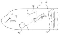
[0102]In FIGS. 4A and 4B, the present invention can be seen, applied to a spacecraft, but it may also be applied to a passenger or cargo aircraft.

[0103]In the described embodiment, the spacecraft comprises hybrid propelling means using an oxidizer consisting of liquid nitrous oxide and HTPB fuel (Hydroxyl-terminated polybutadiene).

[0104]The oxidizer tank is arranged just aft of the cockpit 4. The fuel combustion chamber is not illustrated.

[0105]According to the present invention, the convertible tank 6 is a flexible pouch 29 formed of a sealed membrane 30 to contain the fuel and isolate it from the outside environment, arranged in a container 31.

[0106]This pouch 30 covers the inner walls of the container 31. When the pouch 29 is empty, it is folded away, for example by setting up a vacuum inside it to release the inner volume of the container as illustrated in FIG. 4B.

[0107]Liquid nitrous oxide can be stored at ambient temperature, therefore the membrane used 30 does not need to be ...

third embodiment

[0131]FIG. 8 illustrates the present invention applied to a rocket comprising a propelling system with solid fuel and / or oxidizer equipped with a combustion chamber 42, a hatchway 49 is provided in the bottom part of the combustion chamber 42 on the side of the cockpit 4 to allow access to inside the combustion chamber from the cockpit 4.

[0132]The fuel is burnt in the combustion chamber 42 and is evacuated with the exhaust gases via a throat 46 and an exhaust nozzle 44. This combustion chamber 42 can then be converted to accommodation space for the crew by simply closing the throat 46 accessible via the hatchway 49.

[0133]Advantageously, provision may be made to cover the inner surface of the combustion chamber with a membrane 48, which advantageously can be deployed from within the cockpit. The membrane 48 is then protected from the heat produced in the combustion chamber. The membrane insulates the crew from any combustion residues and prevents pollution of the atmosphere in the ro...


PUM


Abstract

An aircraft including a fuselage including a cabin to accommodate persons and / or a load, and a propulsion system. The propulsion system includes at least one tank and / or one combustion chamber, wherein part of the propulsion system can be used as an extension of the cabin to accommodate persons and / or a load, the part of the propulsion system lying adjacent the cabin and separated from the cabin by a partition.

Description

TECHNICAL AREA AND PRIOR ART[0001]The present invention relates to an aircraft with effective inner volume that can be optimized, in particular to an airplane or spacecraft and to the use of part of a combustion system to optimize the usable space for passengers or goods, and to a method to optimize the usable space of an aircraft.[0002]Aircraft, in particular airplanes and spacecraft, comprise a fuselage forming a shell which contains a cabin for passengers and / or load compartment and a fuel tank.[0003]Cabin volume is limited. Yet for economic reasons it is sought to increase this volume, without however increasing aircraft weight, its manufacturing costs and its fuel consumption.[0004]Aircraft fuel tanks are designed to allow aircraft to travel long distances. Yet an aircraft can also be solely used for short or medium haul flights. In this case, the fuel tank is not completely filled. This void space is dead space since it is not used during these short or long-range flights, whe...

Claims


Application Information

Patent Timeline
IPC IPC(8): B64G1/60B64C1/00B64D37/04B64D9/00B64C1/18B64C1/20B64D13/00B64G1/40B64D11/00B64D11/06
CPCB64C1/068B64D11/00B64D37/04Y02T50/46B64G1/402B64G1/60Y02T50/44B64G1/14Y02T50/40B64G1/4021
Inventor SMITH, GARRETT
Owner AIRBUS