Sensor

a sensor and sensor technology, applied in the field of sensors, can solve the problems of poor reproducibility, multiple compelling needs remain unmet, and biomolecules typically suffer, and achieve the effect of reducing sensitivity

Inactive Publication Date: 2010-07-08
CRANFIELD UNIVERSITY +1
View PDF2 Cites 3 Cited by
  • Summary
  • Abstract
  • Description
  • Claims
  • Application Information

AI Technical Summary

Benefits of technology

[0016]This provides a detection methodology which allows for the specific measurement of one compound present in a complex mixture without the use of protective coatings and loss of sensitivity using high binding affinity synthetic receptors immobilised on a microsensor.

Problems solved by technology

Despite recent advances in PoC testing, several compelling needs remain unmet.
Due to their biological derivation, these biomolecules typically suffer from a number of limitations when used in sensing applications, for example, poor reproducibility, instability during manufacture, sensitivity to environmental factors, such as pH, ionic strength, temperature etc., and problems associated with the sterilisation process.
This approach may therefore help to reduce the electrochemical signal due to the interferents and enable the desired signal arising from the presence of the analyte which is to be detected to be measured, but can considerably reduce the sensitivity of the sensor and increase the response time of the sensor.

Method used


Image

  • Sensor
  • Sensor
  • Sensor

Examples


example 1

Sensor Preparation

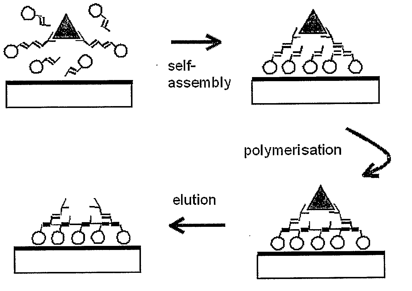
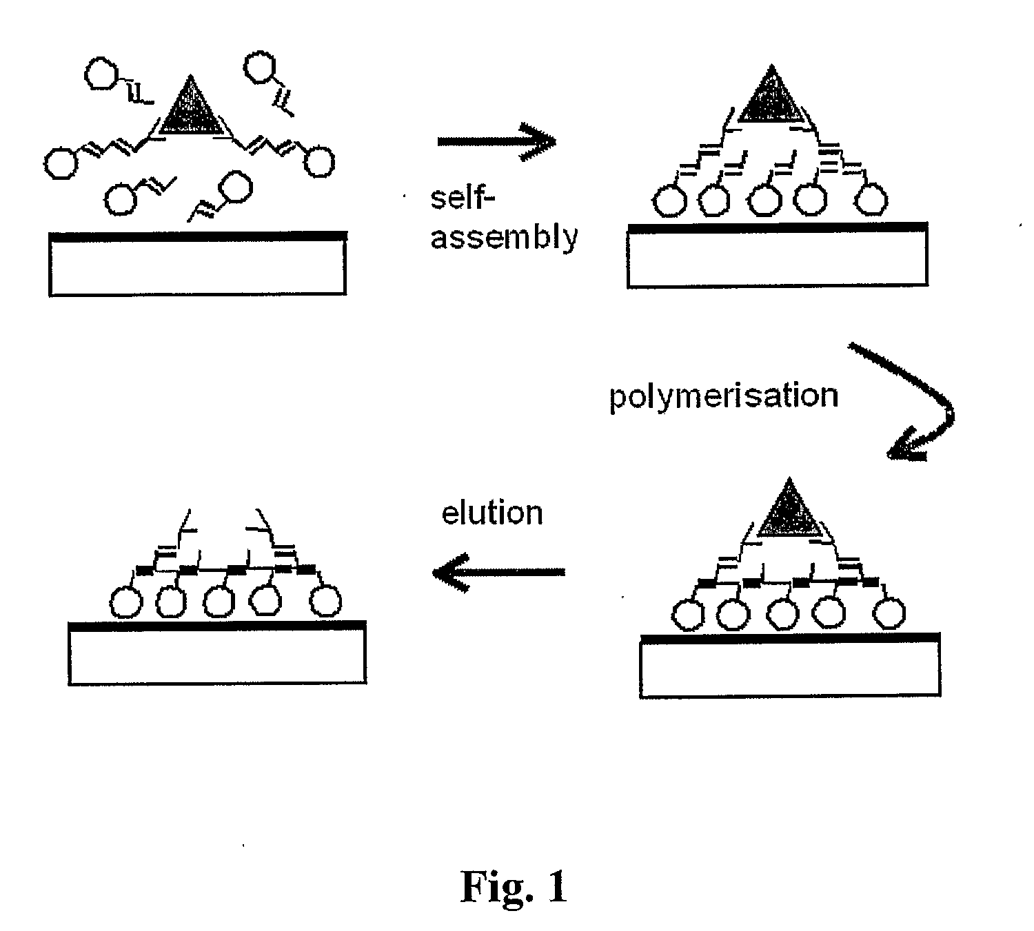
[0052]A sensor was prepared by microfabricating a sensor chip and immobilising a MIP on the transducer using the methodology discussed in WO 2005 / 075995 and WO 2006 / 120381.

[0053]Specifically, to ensure the robust attachment of the MIP layer to the electrode surface as well as gain control over the polymer formation, the polymerisation initiator was firstly anchored to the electrodes. Clean oxidised platinum electrodes were exposed to 3% 3-aminopropyl triethoxysilane in dry toluene for 3 hours in order to introduce amino functionalities at the sensor surface. The polymerisation initiator 4,4′-azobis(cyanovaleric acid) was then covalently attached to the amino layer via carbodiimide coupling by exposing the derivatised sensor to a mixture of 20 mM 4,4′-azobis(cyanovaleric acid), 17 mM N-(3-dimethylaminopropyl)N′-ethylcarbodiimide and 28 mM 1-hydroxybenzotriazole. The reaction was left to take place at room temperature in the dark for 5 hours. The derivatised electrod...

example 2

Sensor Evaluation

[0055]Samples of phosphate-buffered saline containing the anaesthetic propofol in the presence of the interferents uric acid and ascorbic acid were introduced to the MIP and the analyte and interferents were allowed to bind to the MIP. The MIP having the bound analyte and interferents was then washed with phosphate-buffered saline (140 mM NaCl, 10 mM phosphate). Measurements were taken using an amperometric transducer at varying times and the results are shown in FIG. 3.

[0056]FIG. 3A shows the signal of the interferents alone with no propofol (labelled “0 uM”), and the interferents in the presence of 135 μM of propofol (labelled “135 uM”). FIG. 3B shows a region of graph (A) in greater detail illustrating the sharp drop in signal due to the rapid removal of the weakly bound interferents and the slow signal decrease in the presence of propofol. In this example, the signal 30 s following the start of the washing step was taken to be a measure of the concentration of t...


PUM

PropertyMeasurementUnit
voltageaaaaaaaaaa
thickaaaaaaaaaa
pHaaaaaaaaaa

Abstract

This invention relates to a sensor and in particular to a sensor for the detection of biologically important species. Specifically, the invention provides a method for detecting an analyte in the presence of at least one interferent in a sample. The method comprises the steps of providing a sensor having a transducer and a receptor layer in communication with the transducer, in which the receptor layer comprises a material for absorbing the analyte; exposing the receptor layer to the sample; treating the receptor layer to remove selectively the at least one interferent; and measuring the signal from the transducer. The treatment step is performed by applying a change in potential, a change in pH or a change in temperature to the receptor layer, by washing the receptor layer, by irradiating the receptor layer, or a combination thereof.

Description

TECHNICAL FIELD[0001]This invention relates to a sensor and in particular to a sensor for the detection of biologically important species.BACKGROUND ART[0002]Modern healthcare relies extensively on a range of chemical and biochemical analytical tests on a variety of bodily fluids to enable diagnosis and management of disease. Medical and technological advances have considerably expanded the scope of diagnostic testing over the past few decades. Moreover, an increasing understanding of the human body, together with the emergence of developing technologies, such as microsystems technology and nanotechnology, are expected to have a profound impact on diagnostic technology.[0003]Increasingly, diagnostic tests in hospitals are carried out at the point-of-care (PoC), in particular, in situations, where a rapid response is a prime consideration and therapeutic decisions have to be made quickly. Despite recent advances in PoC testing, several compelling needs remain unmet. Many of the prese...

Claims


Application Information

Patent Timeline
Patent Type & Authority Applications(United States)
IPC IPC(8): G01N33/50
CPCA61B5/1427A61B5/14539A61B5/14546Y10T436/203332A61B5/4821G01N33/54373A61B5/1486A61B5/15003A61B5/150992A61B5/153G01N27/404G01N2600/00
Inventor PILETSKY, SERGEY ANATOLIYOVICHHENRY, YVES FREDERICKARIM, KHALKULAITENBERGER, PETER GEORG
Owner CRANFIELD UNIVERSITY
Why Eureka
Try Eureka