Volumetric error compensation system with laser tracker and active target

a technology of laser tracker and error compensation system, which is applied in the field of measuring system, can solve the problems of reducing the accuracy of the tool throughout its working volume, difficult to minimize the dimensional positioning error of the machine tool, and the inability to accurately adjust the rotational axis, so as to achieve accurate rotational axis alignment and repeatability, fast and highly accurate compensation of the machine tool, and easy and far more affordable

a technology of laser tracker and error compensation system, which is applied in the field of measuring system, can solve the problems of reducing the accuracy of the tool throughout its working volume, difficult to minimize the dimensional positioning error of the machine tool, and the inability to accurately adjust the rotational axis, so as to achieve accurate rotational axis alignment and repeatability, fast and highly accurate compensation of the machine tool, and easy and far more affordable

US20100176270A1Active Publication Date: 2010-07-15AUTOMATED PRECISION INC

Image

  • Volumetric error compensation system with laser tracker and active target
  • Volumetric error compensation system with laser tracker and active target
  • Volumetric error compensation system with laser tracker and active target

Examples


Embodiment Construction

[0034]The present invention will now be described more fully hereinafter with reference to the accompanying drawings, in which preferred embodiments of the invention are shown. This invention, however, may be embodied in many different forms and should not be construed as limited to the embodiments set forth herein. Rather, these embodiments are provided so that this disclosure will be thorough and complete, and will fully convey the scope of the invention to those skilled in the art.

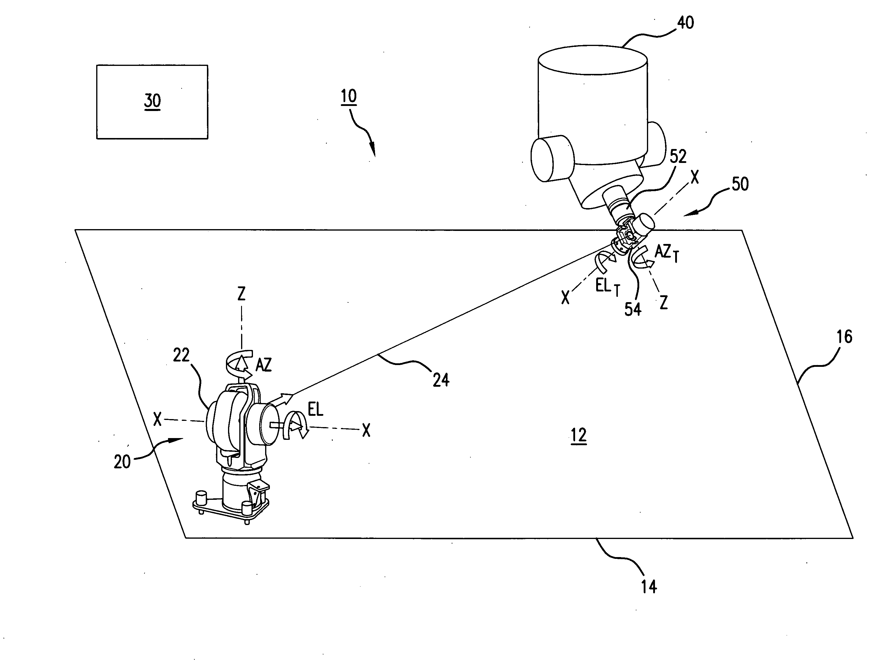
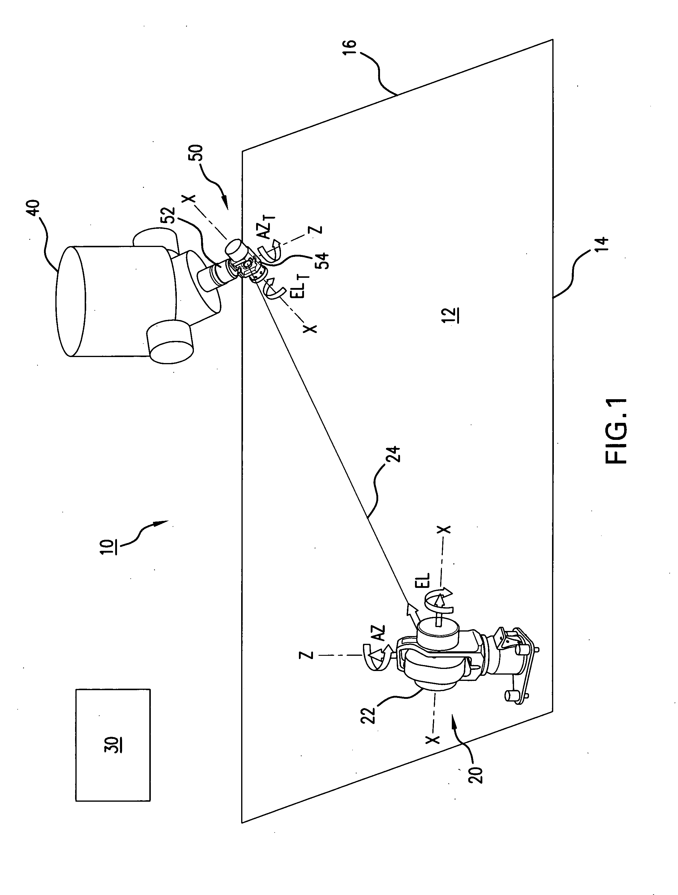
[0035]FIG. 1 is a schematic diagram illustrating a precision, coordinate measurement system in a large-scale machining facility which incorporates an exemplary embodiment of the active target of the present invention. For greater clarity of illustration, the structural features and machinery customarily associated with such machining facility have not been shown. These structural features, machinery and related elements are known to those skilled in the art.

[0036]A large-volume work space 10 includes a ...


PUM


Abstract

A volumetric error compensation measurement system and method are disclosed wherein a laser tracker tracks an active target as the reference point. The active target has an optical retroreflector mounted at the center of two motorized gimbals to provide full 360 degree azimuth rotation of the retroreflector. A position sensitive detector is placed behind an aperture provided at the apex of the retroreflector to detect the relative orientation between the tracker laser beam and the retroreflector by measuring a small portion of the laser beam transmitted through the aperture. The detector's output is used as the feedback for the servo motors to drive the gimbals to maintain the retroreflector facing the tracker laser beam at all times. The gimbals are designed and the position of the retroreflector controlled such that the laser tracker always tracks to a pre-defined single point in the active target, which does not move in space when the gimbals and / or the retroreflector makes pure rotations. Special mechanism and alignment algorithm are used in the gimbal design and retroreflector centering alignment to achieve accurate rotational axis alignment and repeatability.

Description

REFERENCE TO RELATED APPLICATION[0001]The present application claims priority benefit of U.S. Provisional Application No. 61 / 193,932, entitled Volumetric Compensation System with Laser Tracker and Active Target, filed Jan. 9, 2009.BACKGROUND OF THE INVENTION[0002]1. Field of the Invention[0003]The present invention relates generally to a measuring system. In particular, the system and method of the invention are directed to a position measuring system incorporating a laser tracker and an active target. The active target of the position measuring system is capable of 360 degree rotational tracking range to maintain alignment with the tracker laser beam at all times. The position measuring system offers unique advantages in manufacturing processes wherein the position of the machine or machine tool must be precisely determined and any positional errors due to changes in the temperature, mechanical alignment or the like can be detected and corrected.[0004]2. Related Art[0005]Precision ...

Claims


Application Information

Patent Timeline
15 Jul 2010
Publication
US20100176270A1
IPC
G01J1/20; G01C3/08
CPC
B25J9/1692; G01S7/48; G01S17/88; G01S17/66; G01S17/74; G01S7/481
Inventors
LAU, KAM C.; LIU, YUANQUN