Controller for motor drive control system
- Summary
- Abstract
- Description
- Claims
- Application Information
AI Technical Summary
Benefits of technology
Problems solved by technology
Method used
Image

Examples
embodiment 1
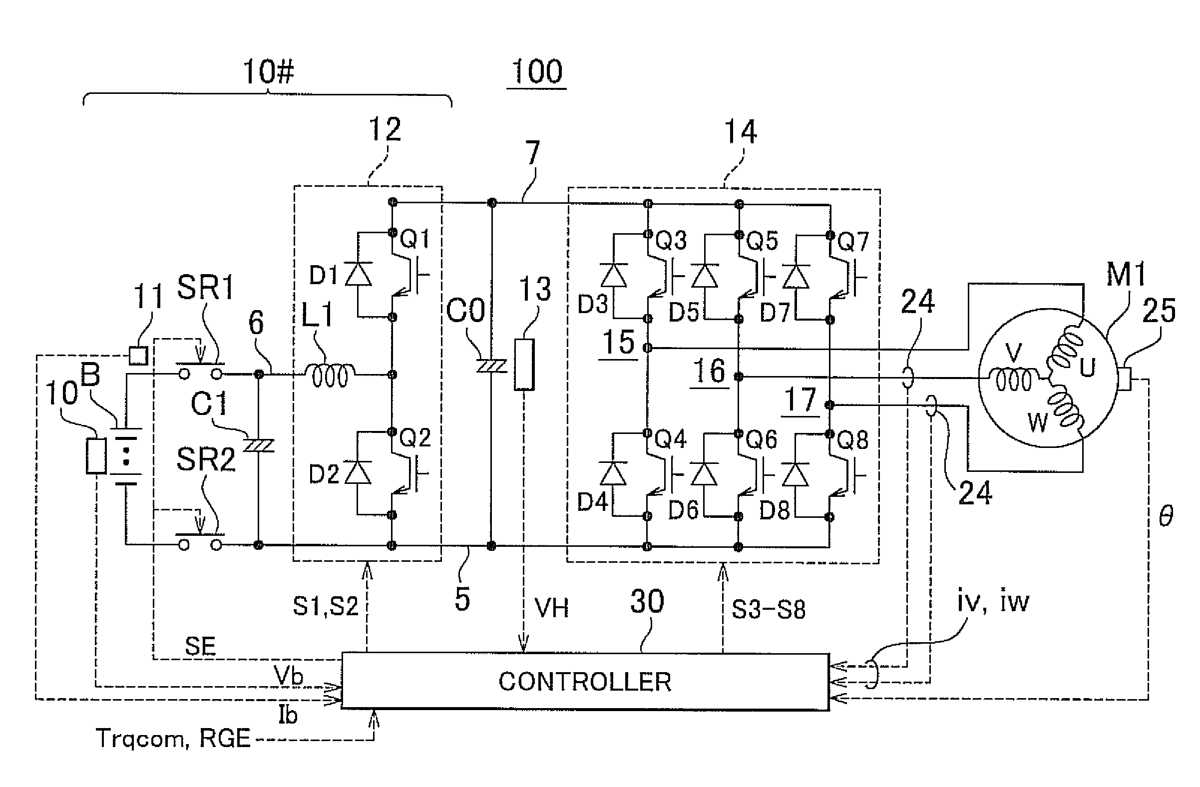
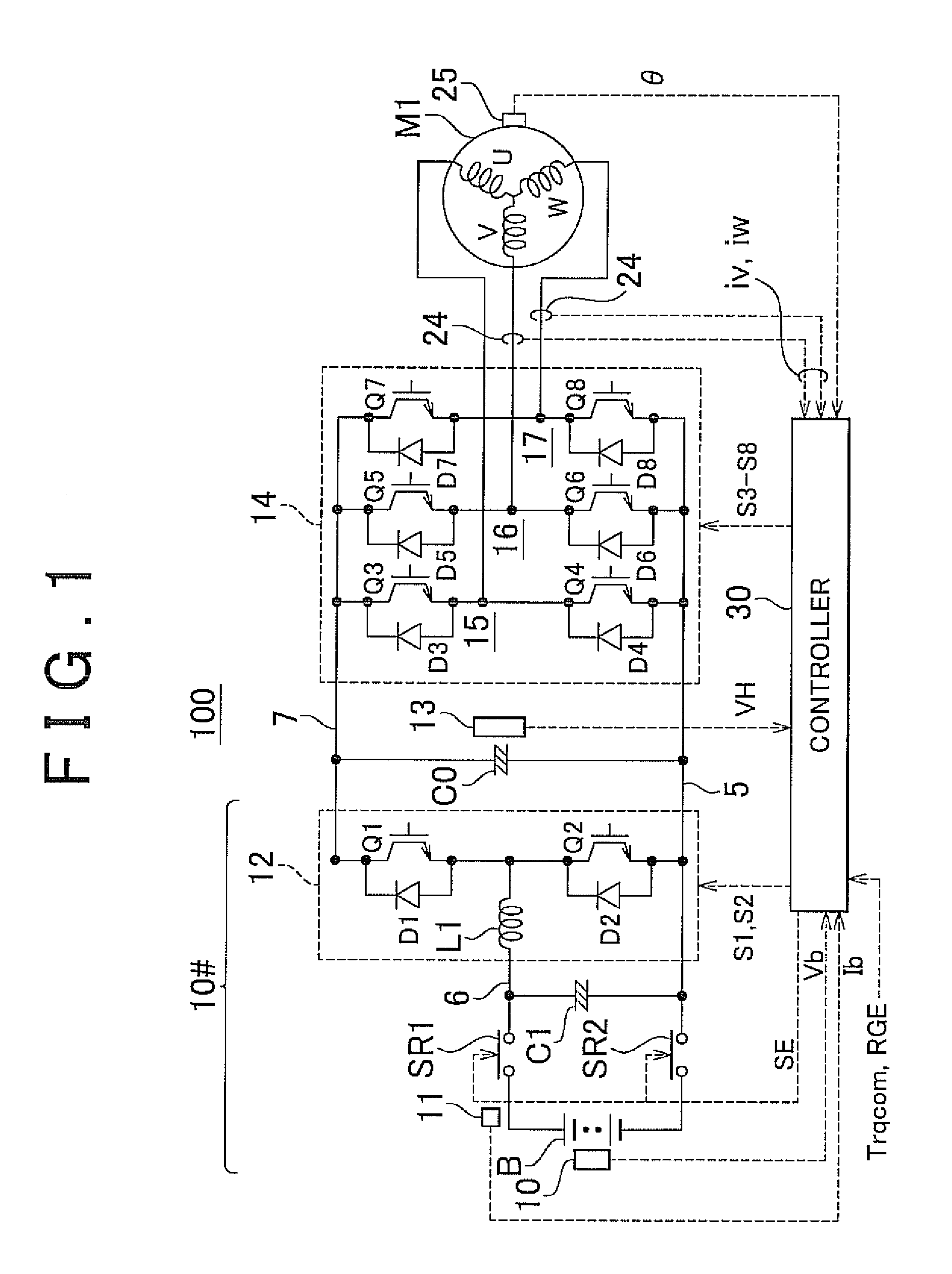
[0051 will be explained below. First, the entire configuration of motor control will be described. FIG. 1 is a configuration diagram of the entire motor drive control system that uses the controller for the AC motor of an embodiment of the invention.
[0052]Referring to FIG. 1, a motor drive control system 100 is provided with a DC voltage generation unit 10#, a smoothing capacitor C0, an inverter 14, an AC motor M1, and a controller 30.
[0053]The AC motor M1 is, for example, a drive motor for generating a torque for driving drive wheels of an electric vehicle (an automobile in which vehicle drive power is generated by electric energy, such as a hybrid automobile, an electric automobile, and a fuel cell vehicle). Alternatively, the AC motor M1 may be configured to have a function of a generator driven by an engine or may be configured to have the functions of both a motor and a generator. Furthermore, the AC motor M1 may operate as a motor with respect to an engine, for example, may be...
embodiment 2
[0153]Accordingly, in Embodiment 2, a technique will be described by which the smoothing processing is conducted only with respect to one current command value from among the d-axis and q-axis current command values, and the other current command value is calculated from the equation representing the relationship between the output torque and the d-axis and q-axis current command values. With such a configuration, it is possible to ensure the continuity of the current command values and also to ensure the target torque.
[0154]The torque T and the d-axis and q-axis current command values Id, Iq generally satisfy the relationship represented by Equation (4) below.
T=N{(Ld−Lq)×Id+Φ}×Iq (4)
[0155]N: a pair of poles;
[0156]Ld: d-axis impedance;
[0157]Lq: q-axis impedance; and
[0158]Φ: magnetic flux of permanent magnet.
[0159]Here, the pair of poles N, d-axis and q-axis impedances Ld, Lq, and magnetic flux Φ of permanent magnet are motor constants of the AC motor M1 and are set correspondingly ...
embodiment 3
[0174 will be explained below. In the current command correction control in the PWM control in Embodiments 1 and 2, the current command values Idcomf, Iqcomf after the correction essentially follow at all times the Idcom, Iqcom, which are the original current command values, with the passage of time. However, due to fluctuations of vehicle state or motor constants in the course of the current command control, it is possible that the current command values Idcomf, Iqcomf after the correction will be unable to follow the Idcom, Iqcom, which are the original current command values, at all times. In such a state, the aforementioned current command line cannot be followed and therefore the operation in a state with poor efficiency will be maintained.
[0175]Accordingly, in Embodiment 3, a technique will be explained by which the decrease in efficiency is inhibited by returning to the original current command in a case where the difference in current commands between a state before the corr...
PUM
 Abstract
Description
Claims
Application Information
 - Generate Ideas
- Intellectual Property
- Life Sciences
- Materials
- Tech Scout
- Unparalleled Data Quality
- Higher Quality Content
- 60% Fewer Hallucinations
Browse by: Latest US Patents, China's latest patents, Technical Efficacy Thesaurus, Application Domain, Technology Topic, Popular Technical Reports.
© 2025 PatSnap. All rights reserved.Legal|Privacy policy|Modern Slavery Act Transparency Statement|Sitemap|About US| Contact US: help@patsnap.com