LED driving circuit, semiconductor element and image display device

a driving circuit and semiconductor technology, applied in the field of technology, can solve the problems of increasing the chip area and heat generation of led current, increasing and increasing so as to increase the number of ic chips to be used and the number of required driving elements

Inactive Publication Date: 2010-07-15
RENESAS ELECTRONICS CORP
View PDF3 Cites 66 Cited by
  • Summary
  • Abstract
  • Description
  • Claims
  • Application Information

AI Technical Summary

Benefits of technology

[0011]According to typical embodiments of the present invention, the number of elements for driving LEDs with a constant current can be reduced, and the increase in the mounting area can be suppressed even when a high current flows to the LEDs.

Problems solved by technology

However, in the technique disclosed in Patent Document 1, the problem of increase in a chip area and heat generation when the LED current is increased occurs because a plurality of constant-current driving elements (transistors or metal oxide semiconductor field effect Transistors (MOSFETs)) are integrated (made into an Integrated Circuit (IC)) on one chip.
However, in this case, there is a problem that the number of required driving elements is increased, and as a result, the number of IC chips to be used is increased.

Method used


Image

  • LED driving circuit, semiconductor element and image display device
  • LED driving circuit, semiconductor element and image display device
  • LED driving circuit, semiconductor element and image display device

Examples


first embodiment

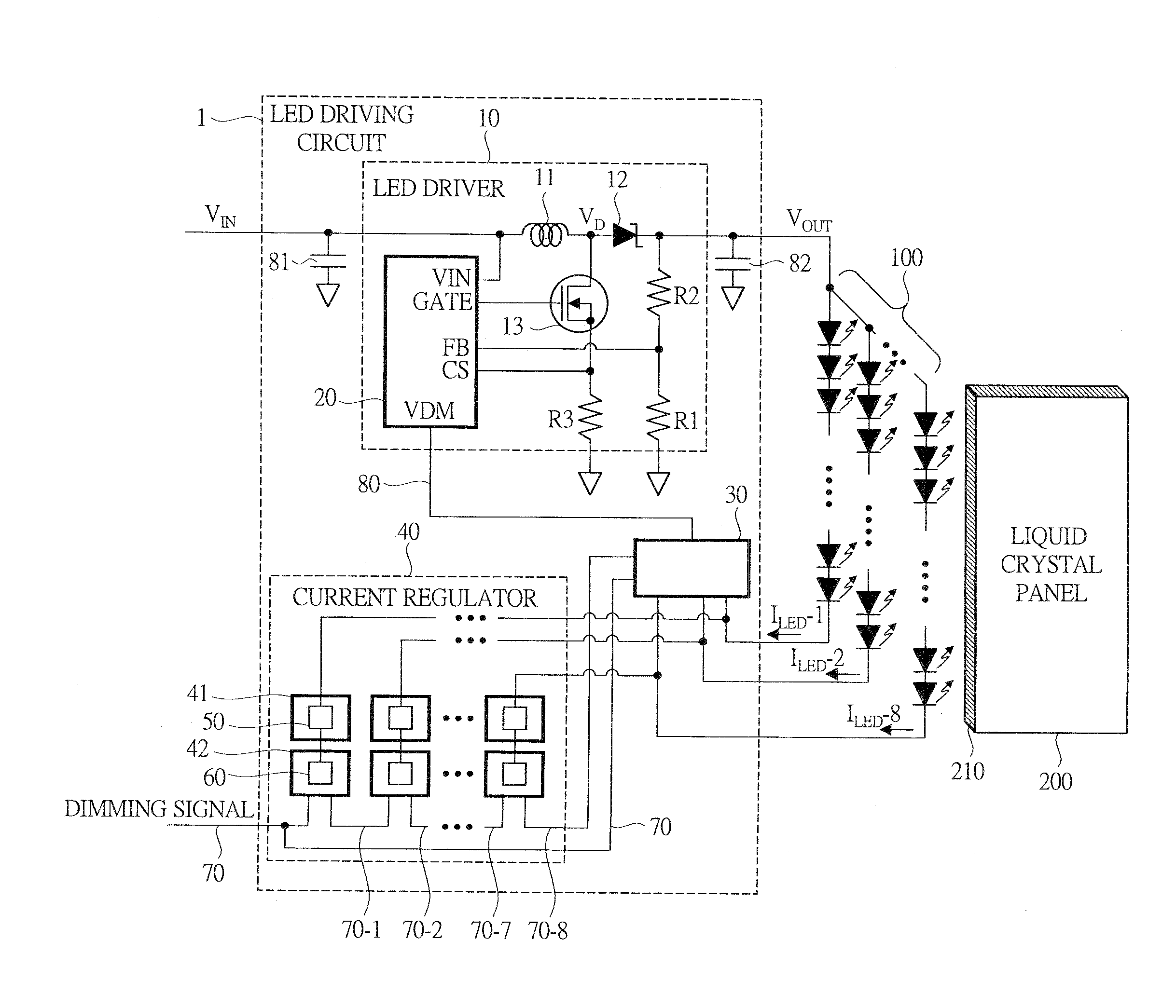
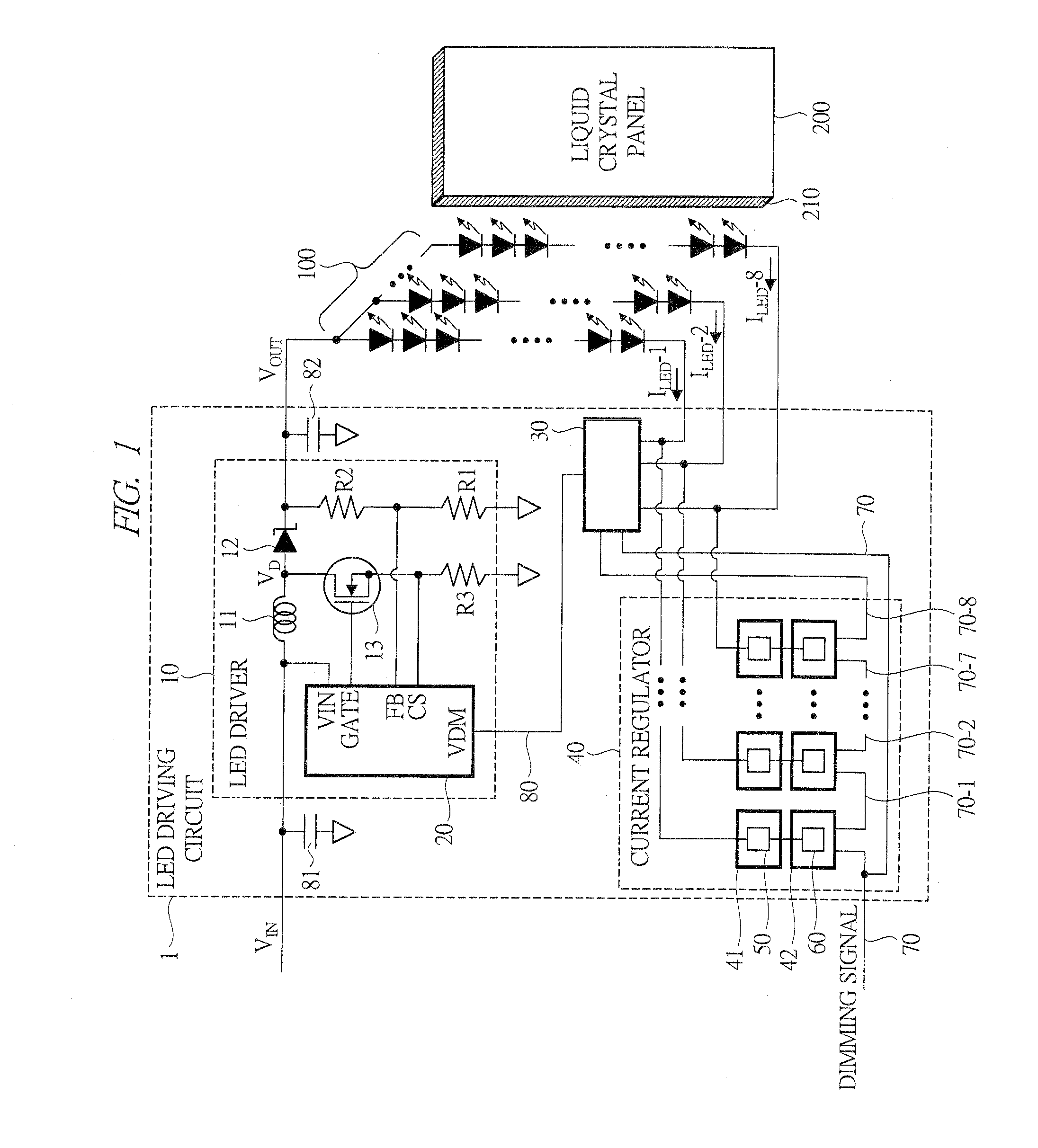
[0040]Hereinafter, an LED driving circuit according to a first embodiment of the present invention will be described with reference to FIG. 1 to FIG. 10. FIG. 1 is a functional block diagram showing a configuration example of the LED driving circuit according to the first embodiment of the present invention. In FIG. 1, an LED driving circuit 1 is connected to an LED array 100, and has an LED driver 10, which is a power supply circuit to supply a voltage to be applied to LEDs, a current regulator 40 for driving the LED array 100 with a constant current, and a lowest-voltage detecting circuit 30.

[0041]The LED array 100 is disposed on a bottom surface 210 side of a liquid crystal panel 200 so as to be arranged in a row as the LED backlight of the liquid crystal panel 200 of an edge light system. The light which comes in from the bottom surface 210 travels in a light guiding plate (not shown) in the liquid crystal panel 200, is diffused by a light diffusion film (not shown) and then ill...

second embodiment

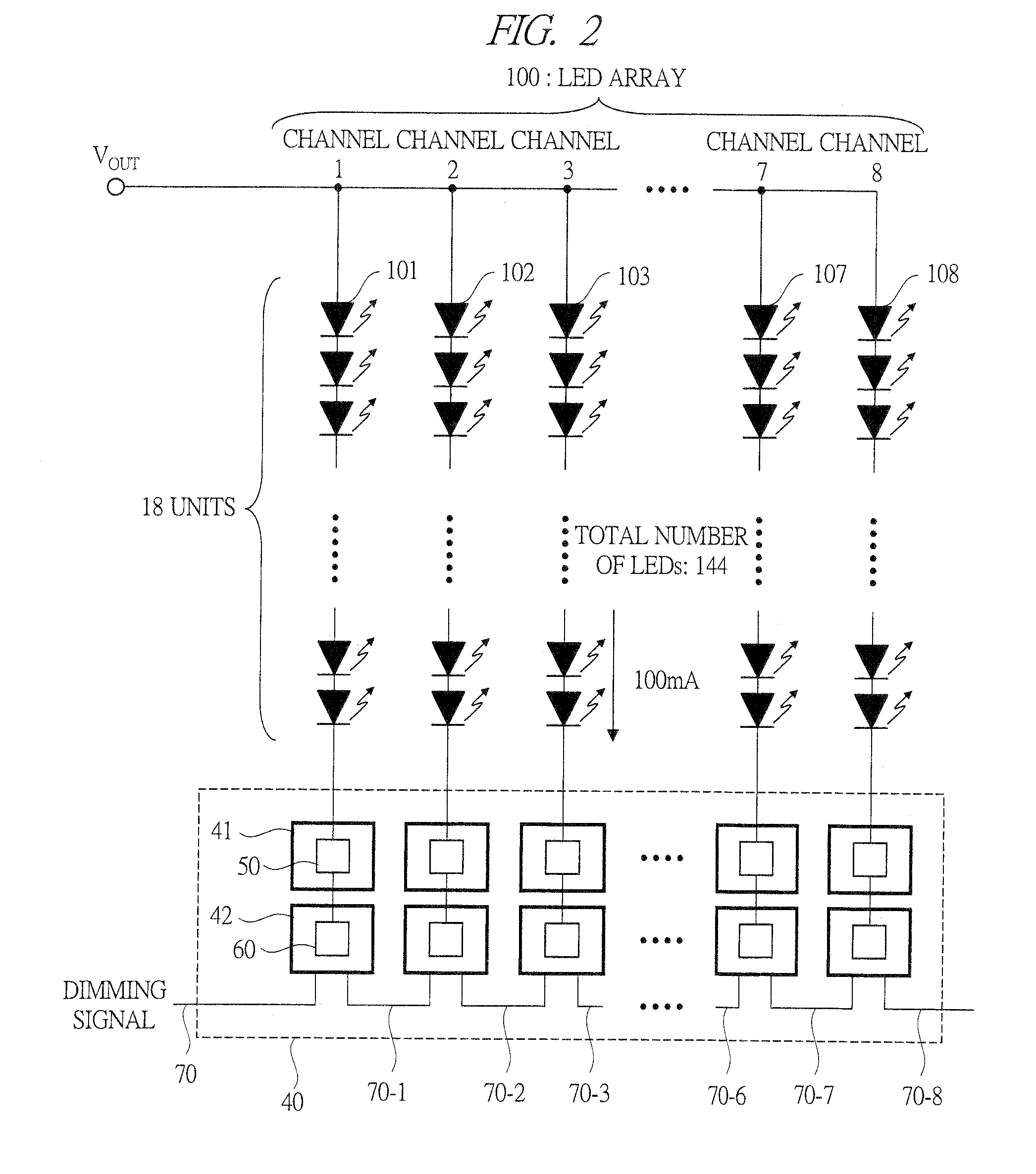
[0083]Hereinafter, an LED driving circuit according to a second embodiment of the present invention will be described with reference to FIG. 11 to FIG. 13. FIG. 11 is a functional block diagram showing a configuration example of the LED array 100 and the current regulator 40 in the LED driving circuit according to the second embodiment of the present invention. The point different from the current regulator 40 of the first embodiment shown in FIG. 2 is that a plurality (four in this embodiment) of constant-current driving elements 50 (50a to 50d) for driving a channel with a constant current and a constant-current control circuit 600 which controls the elements so as to carry out constant-current drive are mounted in one package 400.

[0084]FIG. 12 is a functional block diagram showing a circuit configuration and a configuration example of a package in the case where the plurality of constant-current driving elements 50a to 50d and the constant-current control circuit 600 are mounted ...

third embodiment

[0093]Hereinafter, an LED driving circuit according to a third embodiment of the present invention will be described with reference to FIG. 15 to FIG. 18. FIG. 15 is a functional block diagram showing a configuration example of the LED driving circuit 1 according to the third embodiment of the present invention. The point different from the configuration examples of the first and second embodiments is that the lowest-voltage detecting circuit 30 is incorporated in a constant-current control circuit 610 as described later. In this configuration, the constant-current control circuit 610 detects the smallest value of the drain voltages of the four constant-current driving elements 50a to 50d incorporated in a package 410 and outputs a command signal from a terminal VDM of each package. Accordingly, a command-signal selecting circuit 37 which selects the highest voltage from the command signals (VDM-1 and VDM-2 in the drawing) outputted from the packages 410 is provided, and this is ano...


PUM


Abstract

An LED driving circuit driving an LED array includes: n constant-current driving elements having a vertical structure, each of which is connected to each of LED strings in series and drives the LED string with a constant current; n constant-current control circuits controlling on voltages of the constant-current driving elements so that currents flowing to the LED strings become constant currents; a lowest-voltage detecting circuit to which terminal voltages of the constant-current driving elements on an LED string side are inputted, the lowest-voltage detecting circuit selecting a lowest voltage from among the terminal voltages and outputting a command signal based on difference between the lowest voltage and a predetermined set voltage; and a power-supply control circuit controlling a voltage applied to the LED array to a voltage lower than an initial set voltage based on the command signal.

Description

CROSS-REFERENCE TO RELATED APPLICATION[0001]The present application claims priority from Japanese Patent Application No. JP 2009-003289 filed on Jan. 9, 2009, the content of which is hereby incorporated by reference into this application.TECHNICAL FIELD OF THE INVENTION[0002]The present invention relates to a technique for driving light emitting diodes (LEDs), and in particular to a technique effectively applied to an LED driving circuit which drives an LED array, a semiconductor element used in the LED driving circuit, and an image display device having an LED array and the LED driving circuit.BACKGROUND OF THE INVENTION[0003]LEDs that emit white light have been used for the backlight of a liquid crystal panel for use in a mobile phone and the like. In order to uniform the light-emission luminance of the LEDs without unevenness, the LEDs have to be driven with a constant current so that a predetermined constant current flows to the LEDs.[0004]As a technique related to that, U.S. Pa...

Claims


Application Information

Patent Timeline
Patent Type & Authority Applications(United States)
IPC IPC(8): G06F3/038G09G5/10
CPCG09G3/36
Inventor AKIYAMA, NOBORUHASHIMOTO, TAKAYUKIHIRAO, TAKASHIMATSUURA, NOBUYOSHI
Owner RENESAS ELECTRONICS CORP
Why Eureka
Try Eureka