
Resonant converter equipped with a phase shifting output circuit

Active Publication Date: 2010-07-22
SPI ELECTRONICS
View PDF11 Cites 70 Cited by
  • Summary
  • Abstract
  • Description
  • Claims
  • Application Information

AI Technical Summary

Benefits of technology

[0010]In view of the aforesaid advantages and drawbacks occurred to the conventional circuits set forth above, the present invention aims to provide a multi-output DC / DC converter that provides a higher power density and voltage stability at a lower cost. It employs LLC as the primary output and DAB as the ancillary output to combine the advantages of high efficiency and small size of LLC and DAB, and get resonant inductance of LLC and energy transmission inductance of DAB through leakage inductance of the transformer. Thus a high power density can be achieved, and output of each line can be regulated independently to accomplish a higher accuracy of voltage stability.
[0011]Therefore, the primary object of the present invention is to provide an improved circuit to meet the increasing demand of higher efficiency not achievable by the conventional circuitries and reduce loss and offer desired cross regulations.
[0012]The present invention provides a resonant converter equipped with a phase shifting output circuit. It includes a resonant circuit to receive an input power and regulate to become at least one resonant power, a switch unit to switch an ON period for the input power to pass through the resonant circuit and a power transformation circuit to regulate the resonant power and output a transformed power. The resonant circuit includes a resonant capacitor, a resonant inductor and a parallel inductor bridged between the resonant inductor and the power transformation circuit in a parallel manner. The resonant converter further has a primary output circuit and at least one secondary output circuit. The primary output circuit is connected to the power transformation circuit to regulate the transformed power to become a primary output power. The primary output circuit also is electrically connected to a resonant control unit which receives a feedback signal to generate a resonant control signal. The secondary output circuit is electrically connected to the power transformation circuit to receive the transformed power. The secondary output circuit has a bridge rectification unit and a phase shifting control unit. The phase shifting control unit is electrically connected to the resonant control unit to receive the resonant control signal and regulate to become a phase shifting driving signal. The bridge rectification unit is controlled by the phase shifting driving signal and regulates the transformed power to become a secondary output power. The resonant circuit has a resonant capacitor, a resonant inductor and a parallel inductor coupled in parallel with the power transformation circuit to form an LLC resonant circuit. The secondary output circuit is controlled by phase shifting. By means of the circuit structure set forth above, the efficiency can be enhanced, loss can be reduced, and the input power can be received in a wider voltage range without sacrificing normal operation efficiency. It also provides the multi-output benefit of the LLC circuit.

Problems solved by technology

Hence it is a greater challenge for power supply producers to develop multi-output DC / DC converters with a higher efficiency and greater power density.
But increasing the input voltage range makes topology selection and circuit design more difficult.
This is an issue yet to be fully resolved.
The conventional converter performs switching at a high current or voltage (hard switching) and generates a great switching loss.
However, ACF circuit has a number of inherent drawbacks, such as hard switching off causes a greater switching loss, an extra inductor has to be added and a smaller magnetizing inductance is needed to fully realize the ZVS.
Increasing the inductance reduces the equivalent duty cycle, lowering the magnetizing inductance increases the magnetizing current and results in a greater copper loss and conduction loss.
It also has cross regulation problem.
Hence the conventional PWM (pulse-width modulation) controlled ACF is difficult to meet the duty requirement of a higher efficiency and a greater voltage range at the same time.
As a result, the ACF structure generally does not provide a high efficiency as desired.
On the computer power supply for a lower voltage output application, the DAB circuit has a greater turn-off loss than the LLC circuit.
But it also has its share of drawbacks, such as: 1. MagAmp choke incur magnetic core loss and copper loss; 2. rectification diodes have conduction loss and reverse recovery loss; 3. synchronous rectification of the LLC circuit is greatly affected by MagAmp circuit; 4. its operation frequency is limited because of inherent dead-time effect of the MagAmp circuit.
Hence the LLC+MagAmp circuit cannot achieve a higher efficiency.
Such a structure has cross regulation problem.
Hence regulation accuracy is affected.
Second, when the primary output is only controlled, the ancillary output is regulated merely by coupling that results in a lower accuracy.
But the weighted control has the error shared by two line outputs.
This results in not accurate regulation of either line.
But the cost and size are greater.
Such an approach provides accurate regulation for each output circuit, but total efficiency is lower.

Method used


Image

  • Resonant converter equipped with a phase shifting output circuit
  • Resonant converter equipped with a phase shifting output circuit
  • Resonant converter equipped with a phase shifting output circuit

Examples


first embodiment

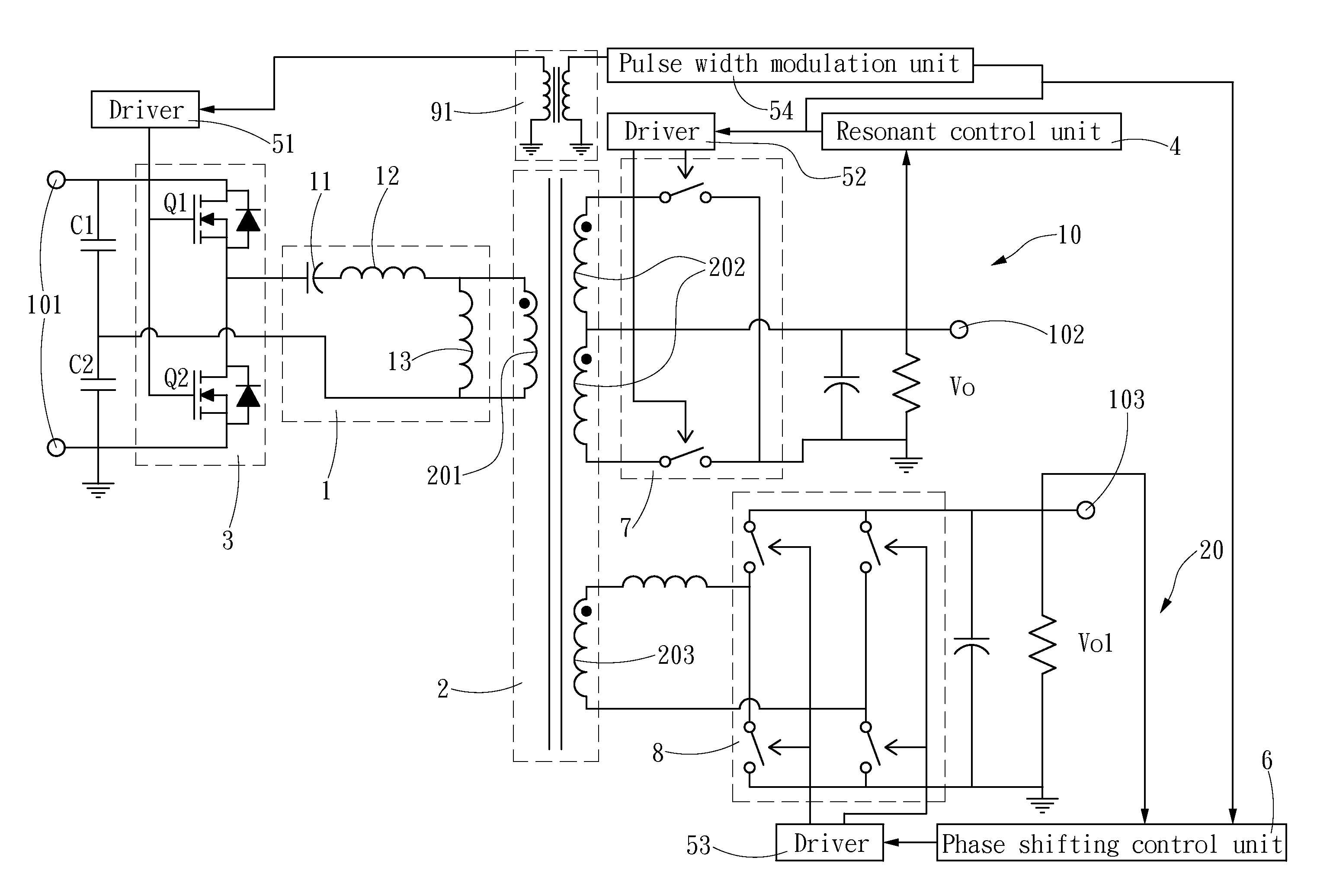
[0030]Please refer to FIG. 9 for the invention. The resonant converter equipped with a phase shifting output circuit of the invention includes a switch unit 3, a resonant circuit 1 and a power transformation circuit 2. In this embodiment, the power transformation circuit 2 is a transformer which has a primary winding 201 and two independent secondary windings 202 and 203. The circuit is connected to a power source 101 to receive input power. The switch unit 3 switches an ON period for the input power to pass through the resonant circuit 1. The switch unit 3 is a bridge circuit consisting of multiple switch elements that are turned on alternately to control the period of the input power passing through the resonant circuit 1. The resonant circuit 1 includes a resonant capacitor 11, a resonant inductor 12 and a parallel inductor 13 bridging the resonant inductor 12 and the power transformation circuit 2 in a parallel manner. The resonant circuit 1 has resonant characteristics to regul...

second embodiment

[0031]The embodiment depicted in FIG. 9 is the basic embodiment of the invention. The invention further has a plurality of secondary output circuits 20. Refer to FIG. 10 for the invention. The power transformation circuit 2 also is a transformer wound with a plurality of coils, including a primary winding 201 and a plurality of independent secondary windings 202, 203, and 204. The secondary winding 202 is connected to the primary output circuit 10. Other secondary windings 203 and 204 are connected respectively to the secondary output circuits 20. The power transformation circuit 2 has a front end (the primary side of the transformer) connecting to the switch unit 3 to control the period of the input power passing through the resonant circuit 1. FIG. 10 shows that the switch unit 3 is a basic half-bridge circuit. Operation of the switch unit 3 also is controlled by the resonant control signal of the resonant control unit 4 (sending to the switch unit 3 through the pulse width modula...


PUM


Abstract

A resonant converter equipped with a phase shifting output circuit includes a resonant circuit to receive input power and regulate to become at least one resonant power, a switch unit to switch an ON period for the input power to pass through the resonant circuit and a power transformation circuit to regulate the resonant power and output a transformed power. The resonant converter further has a primary output circuit and at least one secondary output circuit. The primary output circuit regulates the transformed power to become a primary output power. A resonant control unit captures a feedback signal from the primary output circuit and generates a resonant control signal. A phase shifting control unit receives the resonant control signal and regulate to become a phase shifting driving signal. The secondary output circuit is controlled by the phase shifting driving signal and provides a secondary output power.

Description

FIELD OF THE INVENTION[0001]The present invention relates to a resonant converter equipped with a phase shifting output circuit and particularly to a power transformation circuit adopted resonant and phase shifting control techniques.BACKGROUND OF THE INVENTION[0002]At present regulations on power supply efficiency in various countries are increasingly upgraded to a higher level. For instance, Energy star publishes 80 PLUS standard for multi-output power efficiency of computers and servers. The 80 plus standard has four categories: 80 plus E-star 4.0, 80 plus bronze, 80 plus silver and 80 plus gold. 80 plus gold demands power supply to have efficiency of 87%, 90% and 87% when loading is respectively at 20%, 50% and 100%. As the present power supply of computers and servers generally adopts the structure of PFC+multi-output DC / DC, when the PFC (Power Factor Correction) is at low line, the efficiency usually can reach 94%. To meet the requirement of 80 plus gold, the efficiency of the...

Claims


Application Information

Patent Timeline
IPC IPC(8): H02M3/335
CPCH02M3/33592Y02B70/1433Y02B70/1475Y02B70/10
Inventor NAN, ZHANGHEXU, MINGCHEN, QIAO LIANG
Owner SPI ELECTRONICS
Features
  • Generate Ideas
  • Intellectual Property
  • Life Sciences
  • Materials
  • Tech Scout
  • Unparalleled Data Quality
  • Higher Quality Content
  • 60% Fewer Hallucinations
Learn More