Metal roofing shingle, metal roofing shingle system, and method of installing

Inactive Publication Date: 2010-07-29
SEEM CHARLES T
View PDF24 Cites 17 Cited by
  • Summary
  • Abstract
  • Description
  • Claims
  • Application Information

AI Technical Summary

Benefits of technology

[0015]It is still another object of the present invention to provide a lightweight sheet m

Problems solved by technology

Water penetration between adjacent metal shingles is a well known problem in the art.
Such water problems are most severe in roofs having a moderate pitch, for example between about a 2 in 12 and 4 in 12 roof pitch.
The shallower the pitch, the greater the potential fo

Method used


Image

  • Metal roofing shingle, metal roofing shingle system, and method of installing
  • Metal roofing shingle, metal roofing shingle system, and method of installing
  • Metal roofing shingle, metal roofing shingle system, and method of installing

Examples


Embodiment Construction

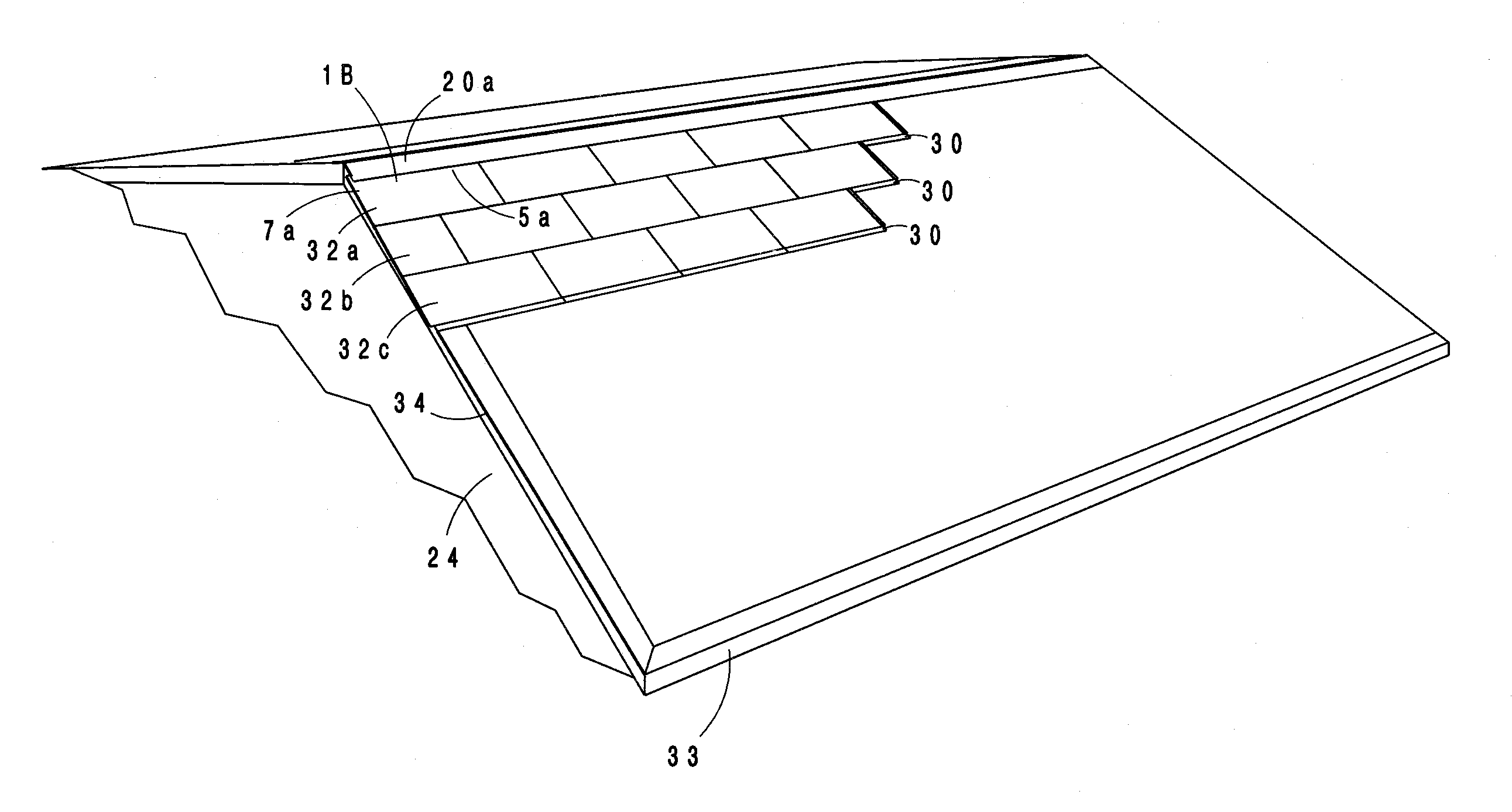
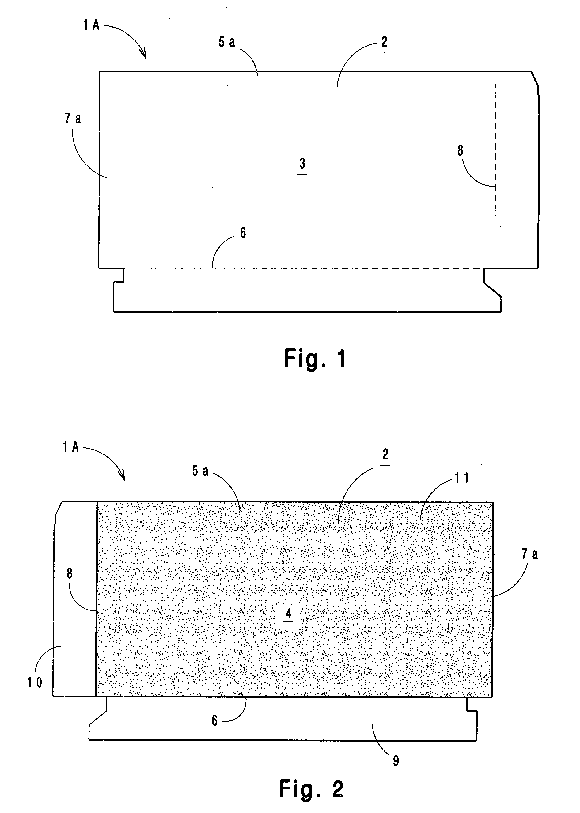
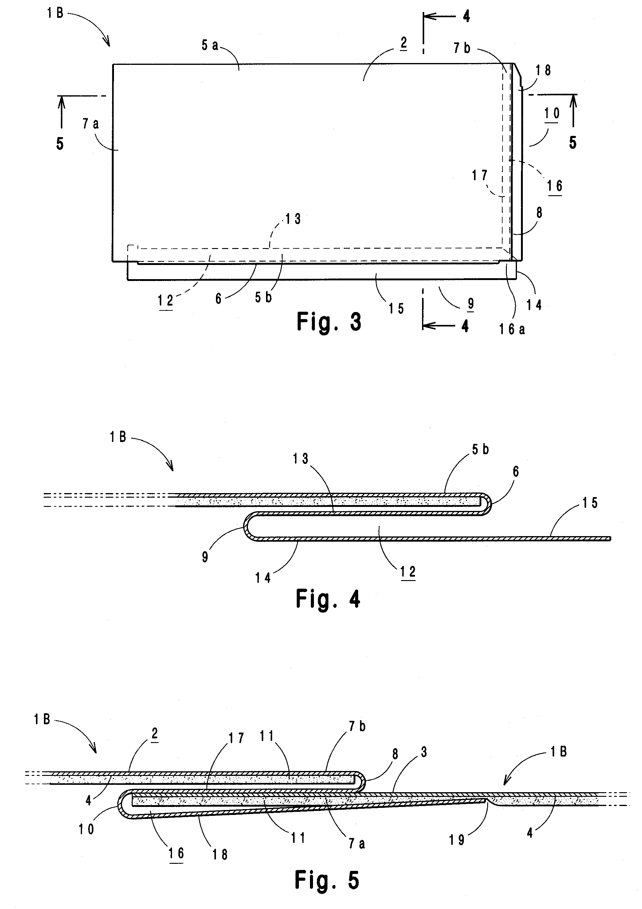
[0039]There have been various attempts in the past to provide metal roofing shingles, for example, shingles manufactured from sheet steel, aluminum, copper or other like metallic materials, to improve service life, insulation characteristics, and appearance in metal roof systems. Such past attempts have had marginal success. State of the art metal shingles are prone to water penetration between adjacent shingles. This is because past mechanical connections between adjacent metal shingles extend along the top or external surface of the shingles where they are exposed to weather conditions. Such exposed joints or connections require the on-sight application of caulks or gaskets along the connection joints to provide watertight integrity. Moreover, the need to apply caulks, adhesives, or like sealants at the job sight is problematic in that, unreliable workers may forget to apply the required sealant, may apply an ineffective amount of sealant material, or apply a poor quality caulk be...


PUM

PropertyMeasurementUnit
Angleaaaaaaaaaa
Lengthaaaaaaaaaa
Distanceaaaaaaaaaa

Abstract

The present invention is directed to a metal roofing shingle system comprising universal flashing installed as either a ridge cap, hip flashing, or valley flashing and including non-visible double-flanged interlock joints that extend beneath the underside surface of the flashing, the interlock joints are adapted to couple with metal shingles; each metal shingle having a planar segment, a first longitudinal edge segment opposite a second longitudinal edge segment that includes a non-visible double-flanged interlock joint that extends beneath the bottom surface of the shingle, and a first transverse edge segment opposite a second transverse edge segment that includes a non-visible double-flanged compression joint that extends beneath the bottom surface of the shingle; and shingle shaping tools.

Description

FIELD OF THE INVENTION[0001]The present invention is directed to a sheet metal roofing system for installation on a pitched roof beginning at the ridge and ending at the eave, and in particular, it is directed to a sheet metal roofing system that includes a) metal shingles with self-sealing, non-visible interlock joints that provide watertight connections between adjacent shingles without the application of sealant materials, b) universal flashing that includes non-visible interlocking joints adapted to couple with the metal shingles when the universal flashing member is installed as either a ridge cap, hip flashing, or valley flashing, and c) shingle shaping tools that reshape edges of the metal shingles; the combination non-visible interlocking joints, reshaped shingle edges, and an applied paint system providing a sheet metal roofing system having the appearance of slate shingles, terracotta tiles, or like roofing materials.[0002]Water penetration between adjacent metal shingles ...

Claims


Application Information

Patent Timeline
IPC IPC(8): E04D1/06E04D13/155E04D15/02B21K23/00E04B1/66E04F19/00E04B1/00
CPCE04D1/18E04D1/28E04D3/40E04D15/02Y10T29/49629E04D1/2914E04D1/2935E04D1/2942
Inventor SEEM, CHARLES T.
Owner SEEM CHARLES T
Why Eureka
Try Eureka