Ignition/ chemical reaction promotion/ flame holding device, speed-type internal combustion engine, and furnace

a technology of flame holding device and ignition reaction, which is applied in the direction of efficient propulsion technology, machines/engines, lighting and heating apparatus, etc., can solve the problems of poor ignition performance, difficult to use a speed-type internal combustion engine, and the measurement of mixing at 1.1 times the stoichiometric ratio cannot be a reliable device as described above, etc., to achieve the effect of spreading and holding flames

Active Publication Date: 2010-07-29
I LAB INC
View PDF22 Cites 34 Cited by
  • Summary
  • Abstract
  • Description
  • Claims
  • Application Information

AI Technical Summary

Benefits of technology

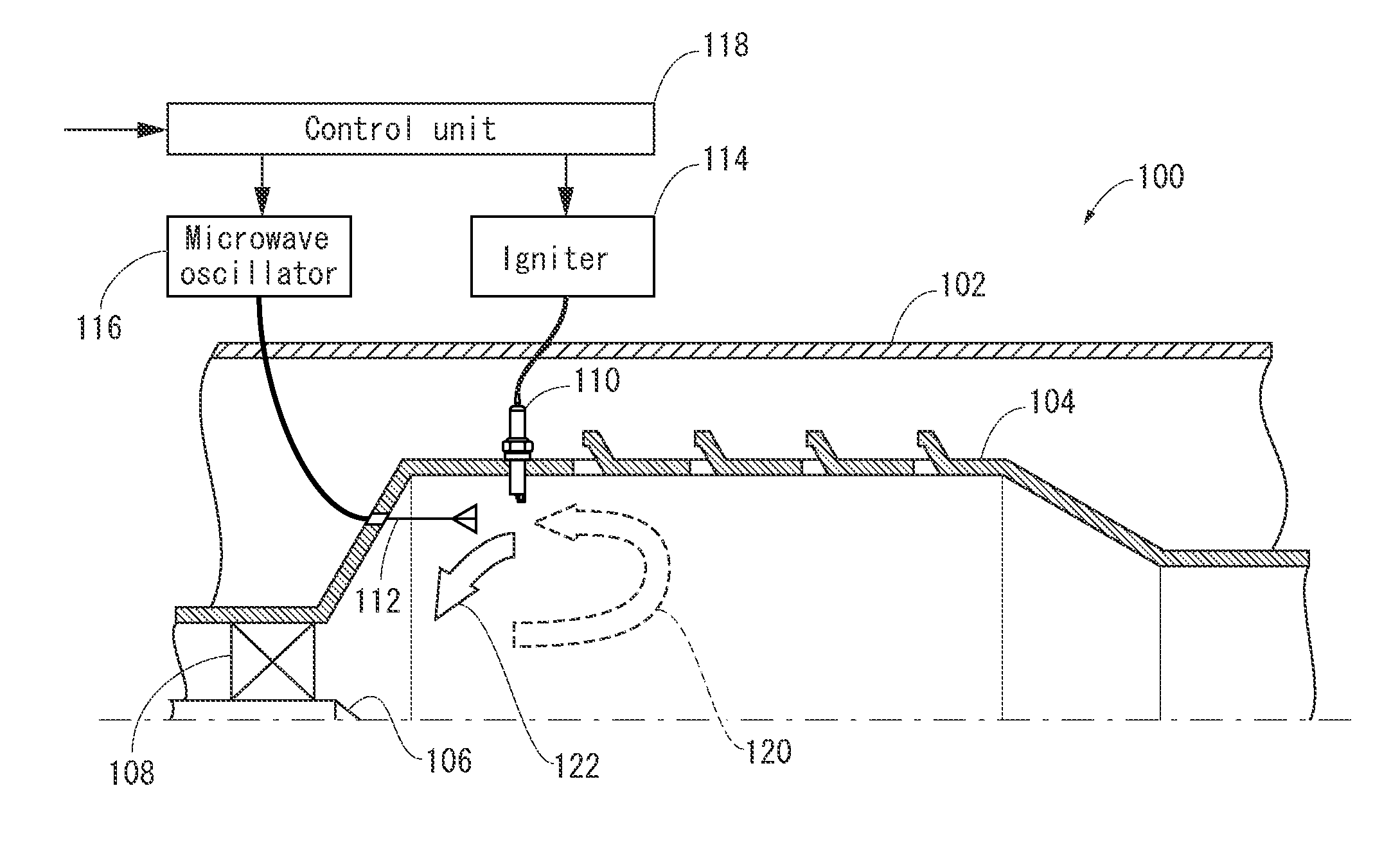
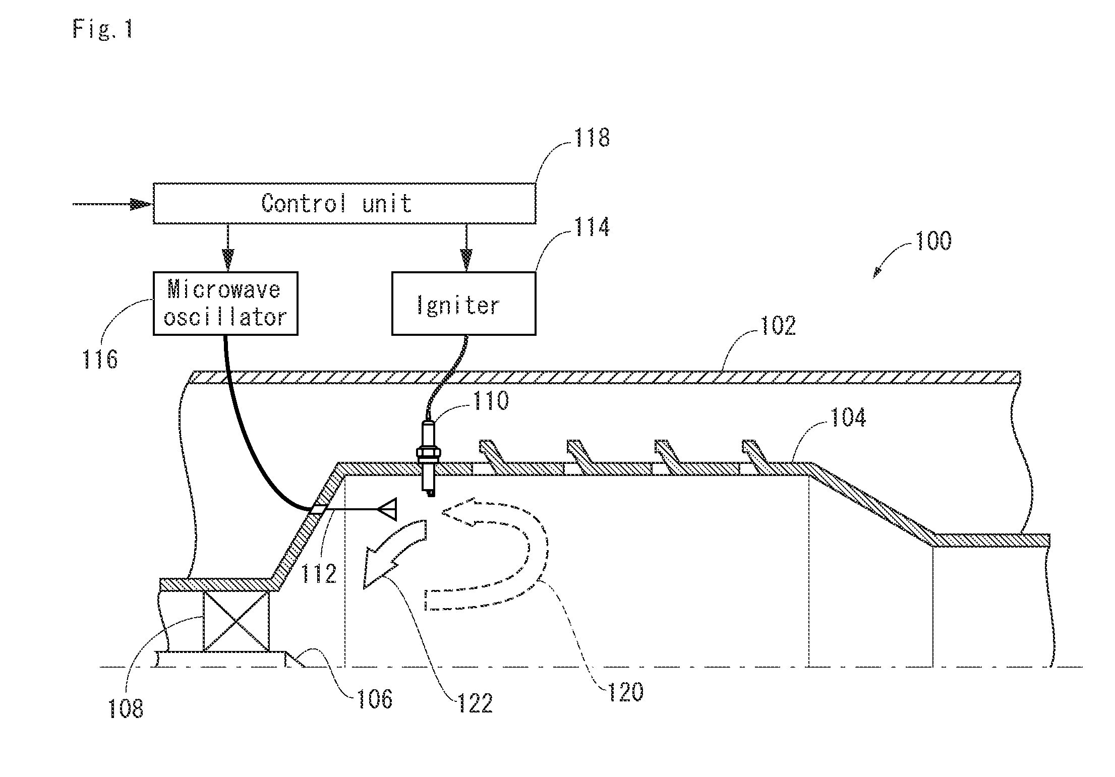
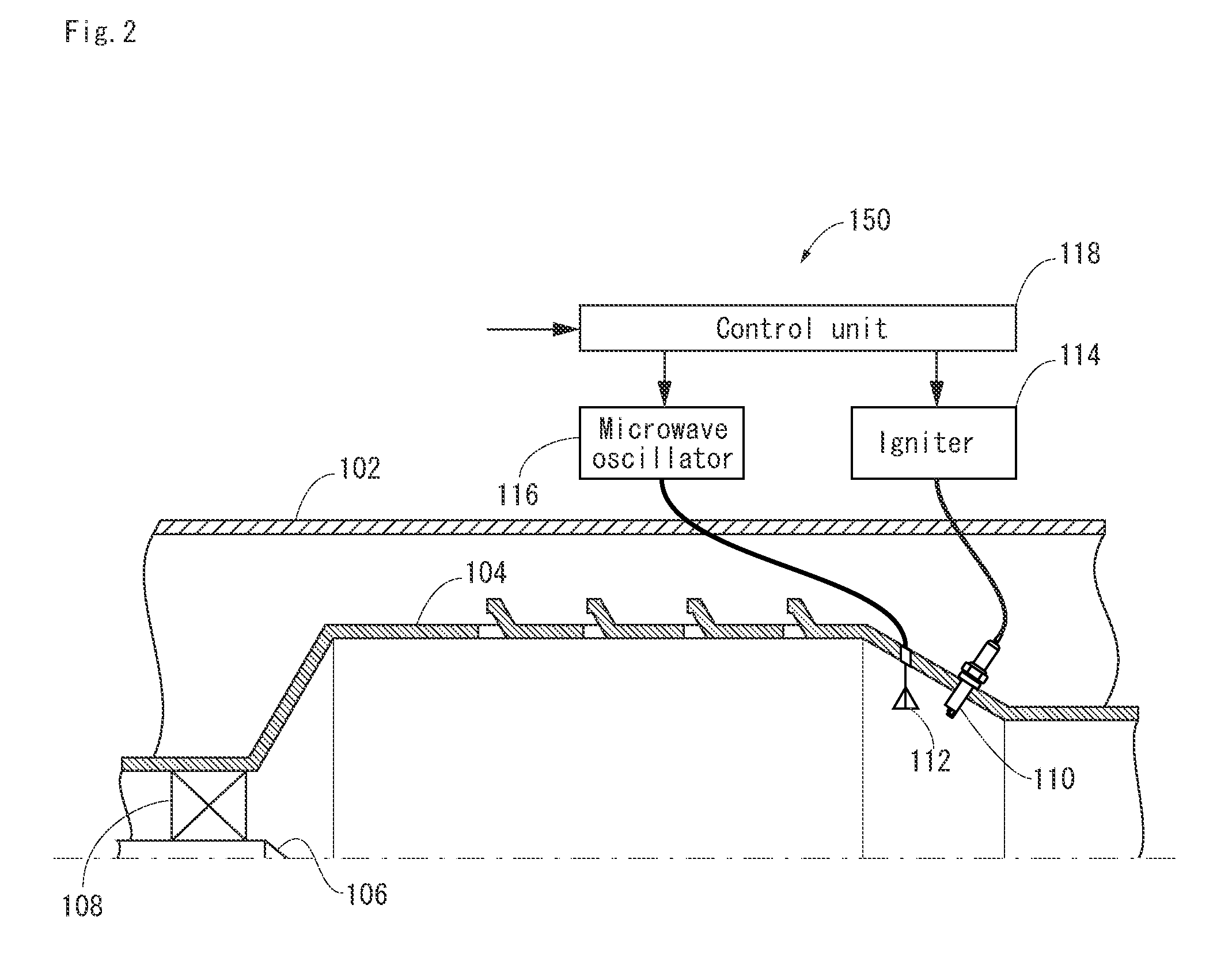
[0020]An ignition / chemical reaction promotion / flame holding device and a high-performance speed-type internal combustion engine that uses this ignition / chemical reaction promotion / flame holding device are provided, whereby ignition and the spreading and maintaining of flames can be dramatically improved in a speed-type internal combustion engine.
[0057]Specifically, it is possible to provide an ignition / chemical reaction promotion / flame holding device and a high-performance speed-type internal combustion engine using this device, whereby combustion and the spreading and holding of flames can be dramatically improved in a speed-type internal combustion engine.

Problems solved by technology

However, these devices have the following problems, which make it difficult to use a speed-type internal combustion engine.
Specifically, since it is difficult to stabilize the fuel concentration, the measure for mixing at 1.1 times the stoichiometric ratio cannot be a reliable device as described above.
Even if mixing is performed in a stable manner, the combustion rate increases with this mixture ratio, but on the other hand, ignition performance is poor.
What is even less desirable is that a large amount of fuel is consumed by this device.
Not only is this an environmental problem, but since more fuel must be prepared in advance, it is extremely disadvantageous for an aircraft, rocket, or spacecraft in which weight is directly tied to flying time, range, or payload weight.
A device for forming a turbulent flow or swirl flow is limited in the range whereby these effects can be achieved.
Specifically, when the disturbance produced in the flow of the working fluid by the flame holder becomes too strong, extinction (extinguishing of flames) occurs and the flames are lost.
When the bulk speed becomes too fast in recirculation, blowing off (flames being blown out) occurs.
In a speed-type internal combustion engine that uses air as an oxidizing agent, the temperature of these flames is the cause of the formation of harmful nitrogen oxide.
In order to perform cooling, a measure such as diverting some of the air supply to a cooling-designated liner must be taken, and efficiency is lost proportionately.
Not only does this lead to a weight increase, but it also has the result of making the hot spots extremely large, making the above-described hot spot problem increasingly worse.

Method used


Image

  • Ignition/ chemical reaction promotion/ flame holding device, speed-type internal combustion engine, and furnace
  • Ignition/ chemical reaction promotion/ flame holding device, speed-type internal combustion engine, and furnace
  • Ignition/ chemical reaction promotion/ flame holding device, speed-type internal combustion engine, and furnace

Examples


second embodiment

[0098]FIG. 4 shows the internal configuration of a combustor 250 according to the second embodiment.

[0099]In this combustor 250, a plurality of spark plugs 110A . . . 110D are attached to the inner liner 104, as shown in FIG. 4. The spark plugs 110A . . . 110D are connected to the igniter 114 via a selector 254. A control unit 256 has a function for controlling the selection of output by the selector 254, in addition to the function of the control device 118 according to the first embodiment.

[0100]An antenna 252 according to the present embodiment may be the same as the antenna 112 according to the first embodiment, but this antenna preferably has a certain degree of directivity in order for the microwaves to reliably reach the location of the discharge gaps of the spark plugs 110A . . . 110D.

[0101]In the present embodiment, during ignition or re-ignition, and also when flame holding is performed using the spark plugs, the selector 254 selects which spark plug will discharge from am...

third embodiment

[0104]FIG. 5 shows the internal configuration of a combustor 300 according to the third embodiment.

[0105]In the present embodiment, the antenna 112 is installed in a position nearer to the center axis than the swirler 108 in the combustor 300, and the spark plug is installed in proximity to the antenna 112, as shown in FIG. 5. In the combustor according to the present embodiment, the inner liner 304 does not have an air intake hole for cooling.

[0106]In the present embodiment, when discharge and microwave pulse radiation is performed and plasma is formed to produce active chemical species, the active chemical species requiring the most time to deactivate out of all the active chemical species flows along with the main flow of the working fluid. This active chemical species causes ignition or flame holding to take place in the vicinity of the center axis, and a distribution of flames is formed such that flames are present only in the vicinity of the center axis. The distribution of th...

fourth embodiment

[0109]FIG. 6 shows the internal configuration of a combustor 350 according to the fourth embodiment.

[0110]The combustor 350 has the same inner liner 304 as the combustor 300 of the third embodiment, as shown in FIG. 6. Instead of the injector 106, the combustor has a pipe 352 through which fuel and air pass, and a nozzle 354 for supplying fuel into the pipe 352.

[0111]In the present embodiment, the spark plug 110 and the antenna 112 are disposed upstream of the swirler 108 on the internal side of the pipe 352. In the combustor 350, combustion is performed in the vicinity of the center axis, similar to the combustor 300 according to the third embodiment.

[0112]In the present embodiment, microwave pulses are repeatedly radiated during flame holding. The cycle of microwave pulse repetition can be determined, e.g., in the following manner. For example, the value is found thus: the distance in the center axial direction of the region over which the active chemical species enlarges without ...


PUM


Abstract

An ignition and chemical reaction accelerator and flame stabilizer and a high-performance speed-type internal combustion engine using this device are provided, whereby ignition and the spreading and holding of flames can be dramatically improved in a gas turbine, a ram machine, a rocket engine, or another speed-type internal combustion engine. An ignition and chemical reaction accelerator and flame stabilizer of a speed-type internal combustion engine comprises a spark plug (110) for preparing charged particles in a predetermined location in a combustor (104) of the speed-type internal combustion engine, and a microwave oscillator (116) and antenna (112) for inducing plasma with a working fluid in the combustor as a starter material by irradiating the charged particles and their surrounding vicinity with microwave pulses; wherein a region in which sufficient conditions for performing combustion are met is formed in the combustor by supplying an active chemical species produced from the working fluid by the effect of the plasma.

Description

TECHNICAL FIELD[0001]The disclosure relates to an ignition / chemical reaction promotion / flame holding device for gas turbines, pulse jet engines, jet propulsion engines that use gas turbines, ram machines, scramjet engines, rocket engines, or other speed-type internal combustion engines; or boilers, flame furnaces, gas fusion furnaces, waste combustion furnaces, or other types of furnaces. The disclosure particularly relates to an ignition / chemical reaction promotion / flame holding in which proper ignition and combustion are ensured using plasma, and also to a speed-type internal combustion engine and furnace that use this ignition / chemical reaction promotion / flame holding device.BACKGROUND OF THE INVENTION[0002]A speed-type internal combustion engine, typified by a gas turbine, is a machine in which a working fluid is accelerated by energy generated by combustion, wherein the working fluid flows through a combustor at a high speed. If the temperature and pressure of the working fluid...

Claims


Application Information

Patent Timeline
Patent Type & Authority Applications(United States)
IPC IPC(8): F02P23/04F02C7/264F02K9/95
CPCF02C7/264F02C7/266F02P15/003F02P15/02F02P15/08F02P23/04F02P23/045F23C99/001F23C2900/99003F23C2900/99005F23R2900/00006F23R2900/00008Y02T50/671F05D2220/10F05D2220/80Y02T50/60
Inventor IKEDA, YUJI
Owner I LAB INC
Why Eureka
Try Eureka