Low-refractive-index film, method of depositing the same, and antireflection film

a low-refractive index, anti-reflection technology, applied in the direction of instruments, optical elements, vacuum evaporation coating, etc., can solve the problems of increased refractive index variation, increased cost of target preparation, and increased risk of sif/sub>4/sub>, so as to achieve uniform optical properties and good anti-reflection function

Inactive Publication Date: 2010-07-29
SONY CORP
View PDF22 Cites 2 Cited by
  • Summary
  • Abstract
  • Description
  • Claims
  • Application Information

AI Technical Summary

Benefits of technology

[0013]According to the method of depositing a low-refractive-index film of the present invention, a low-refractive-index film composed of a fluoride and having a uniform composition distribution can be deposited by a sputtering method. In addition, by appropriately adjusting the composition of MgF2—SiO2, a low-refractive-index film having any optical properties can be obtained.
[0014]According to the low-refractive-index film of the present invention, a low-refractive-index film having uniform optical properties in the film surface can be provided.
[0015]According to the low-refractive-index film of the present invention, an antireflection film having a uniform and good antireflection function in the film surface can be provided.

Problems solved by technology

However, in this method, the composition of a thin film to be prepared varies in the plane, resulting in an increase in the variation in the refractive index.
However, in the case where a MgF2—Si target is prepared, Si and F react with each other at a stage of mixing a MgF2 powder with a Si powder, thereby generating a toxic gas such as SiF4, which is hazardous.
Accordingly, the cost of the preparation of the target increases, and this target is not preferable as a target for forming a low-refractive-index film.
However, even when such a target is used, it is difficult to deposit a low-refractive-index film suitable for an antireflection film.

Method used


Image

  • Low-refractive-index film, method of depositing the same, and antireflection film
  • Low-refractive-index film, method of depositing the same, and antireflection film
  • Low-refractive-index film, method of depositing the same, and antireflection film

Examples


example 1

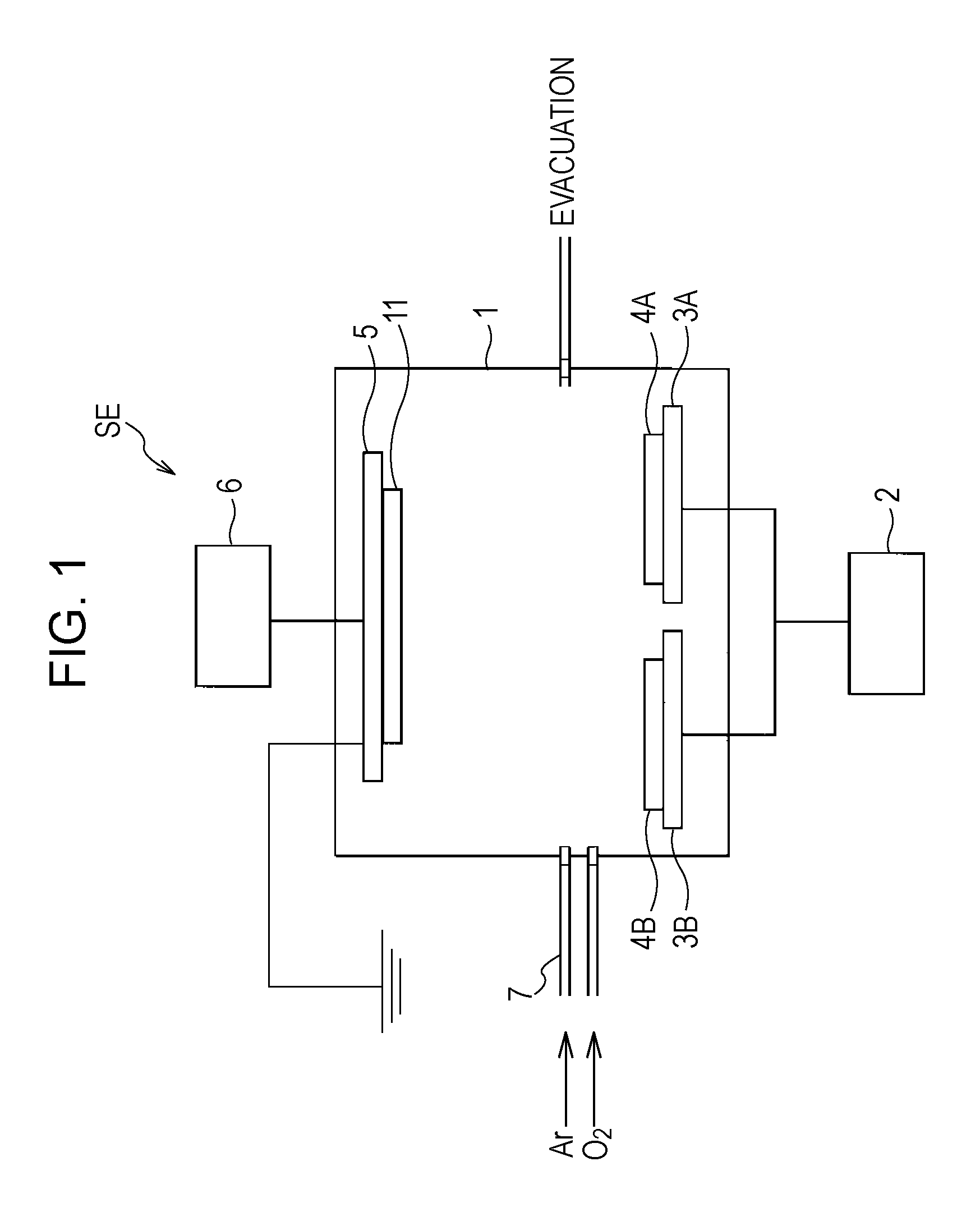
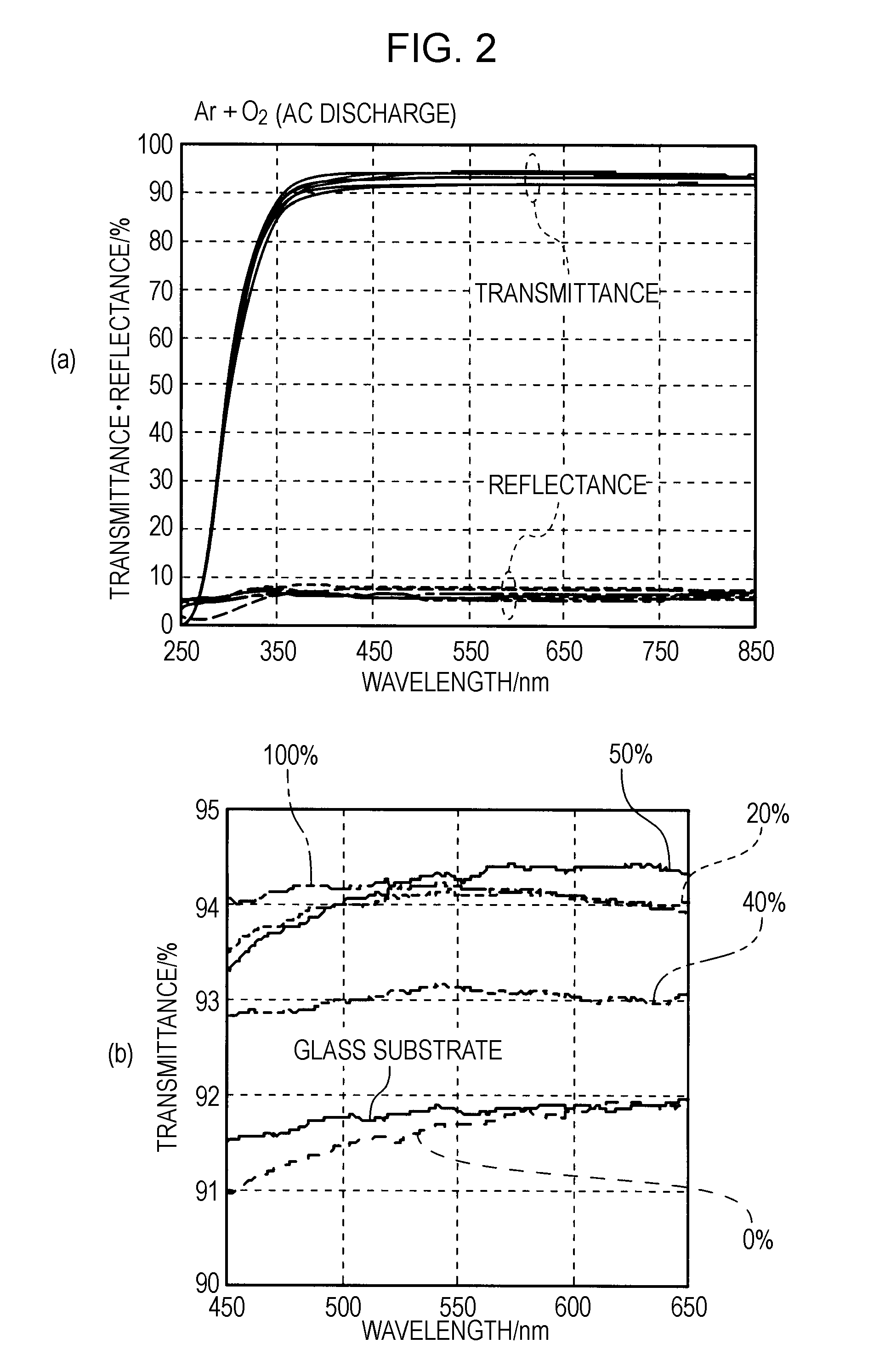
[0033]A description will be made of an example in which low-refractive-index films were deposited by the method of depositing a low-refractive-index film of the present invention using the reactive sputtering apparatus SE shown in FIG. 1. Note that, as for sputtering conditions, targets 4A and 4B: MgF2—SiO2 sintered body (MgF2:SiO2=70:30 atomic percent), sputtering gas: Ar, and reactive gas: O2 were used as common conditions, and the Ar gas was introduced with a back pressure in the vacuum chamber 1 of 5×10⁻⁴ Pa or less, and pre-sputtering was performed. Subsequently, low-refractive-index films were prepared under the deposition conditions below. Note that (O2 gas flow rate ratio)=(O2 gas flow rate) / {(O2 gas flow rate)+(Ar gas flow rate)}×100 (%).

(Deposition Conditions)

[0034]Substrate 11: transparent glass substrate

O2 gas flow rate ratio: 0%, 20%, 40%, 50%, and 100%

Frequency of AC power supply: 90 kHz

Supplied electrical power: 400 W

Total pressure: 0.37 to 0.39 Pa

[0035]Furthermore, s...

example 2

[0047]A description will be made of an example of a deposition of an antireflection film using the reactive sputtering apparatus SE shown in FIG. 1.

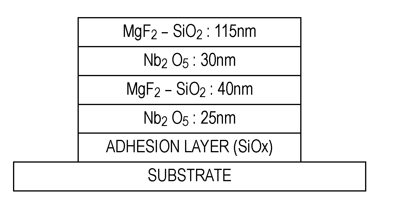
[0048]Here, an antireflection film having the structure shown in FIG. 4 was prepared in the order described below on the basis of the respective deposition conditions below.

(1) Substrate: Glass substrate

(2) Adhesion layer: SiOx

Sputtering target: B-doped polycrystalline Si

Sputtering gas: Ar

Reactive gas: O2

[0049](3) High-refractive-index layer a: Nb2O5

Sputtering target: Metal Nb

Sputtering gas: Ar

Reactive gas: CO2

[0050]Film thickness: 25 nm

(4) Low-refractive-index layer a: MgF2—SiO2

Sputtering targets 4A and 4B: MgF2—SiO2 sintered body (MgF2:SiO2=70:30 atomic percent)

Sputtering gas: Ar

Reactive gas: O2

[0051]Deposition conditions: The same as those used in Sample No. 4 in Example 1

Film thickness: 40 nm

(5) High-refractive-index layer b: Nb2O5

Sputtering target: Metal Nb

Sputtering gas: Ar

Reactive gas: CO2

[0052]Film thickness: 30 nm

(6) Low...


PUM

PropertyMeasurementUnit
electrical poweraaaaaaaaaa
refractive indicesaaaaaaaaaa

Abstract

Provided is a method of depositing a low-refractive-index film, by which a thin film having uniform composition distribution in the film and having a low refractive index can be formed, a low-refractive-index film deposited by the method of depositing a low-refractive-index film, and furthermore, an antireflection film including the low-refractive-index film. In a method of depositing a low-refractive-index film including depositing a low-refractive-index film composed of MgF2—SiO2 on a substrate 11 by a reactive sputtering method, sputtering deposition is conducted using targets 4A and 4B composed of a sintered body of MgF2—SiO2 by applying an alternating voltage with a frequency in the range of 20 to 90 kHz between the substrate 11 and the targets 4A and 4B in an atmosphere of a mixed gas of an inert gas O2.

Description

TECHNICAL FIELD[0001]The present invention relates to a low-refractive-index film deposited by a reactive sputtering method, a method of depositing the same, and an antireflection film including the low-refractive-index film.BACKGROUND ART[0002]In general, in a display device such as a cathode ray tube (CRT) or a liquid crystal display, an antireflection film is provided on a surface on which an image is displayed. This antireflection film is provided in order to reduce reflection of external light to reproduce a preferred image or text information and formed by stacking thin-film materials having different refractive indices.[0003]Such an antireflection film is constituted by stacking, for example, on a transparent film base composed of an organic material, a low-refractive-index layer composed of a low-refractive-index material such as silicon oxide, silicon nitride, or magnesium fluoride and a high-refractive-index layer composed of a high-refractive-index material such as tin ox...

Claims


Application Information

Patent Timeline
Patent Type & Authority Applications(United States)
IPC IPC(8): C09D1/00C23C14/38
CPCC23C14/06C23C14/3464G02B1/115C23C14/34G02B1/11
Inventor TAKETOMO, MIKIHIROKAWASHIMA, TOSHITAKAOSHIMA, YOSHIHIRO
Owner SONY CORP
Why Eureka
Try Eureka