Battery internal short-circuit detection apparatus and method, and battery pack
- Summary
- Abstract
- Description
- Claims
- Application Information
AI Technical Summary
Benefits of technology
Problems solved by technology
Method used
Image
Examples
Embodiment Construction
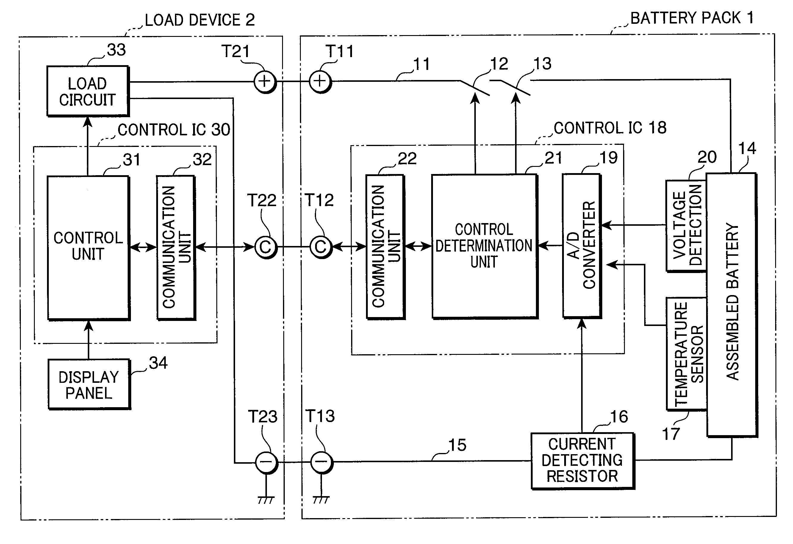
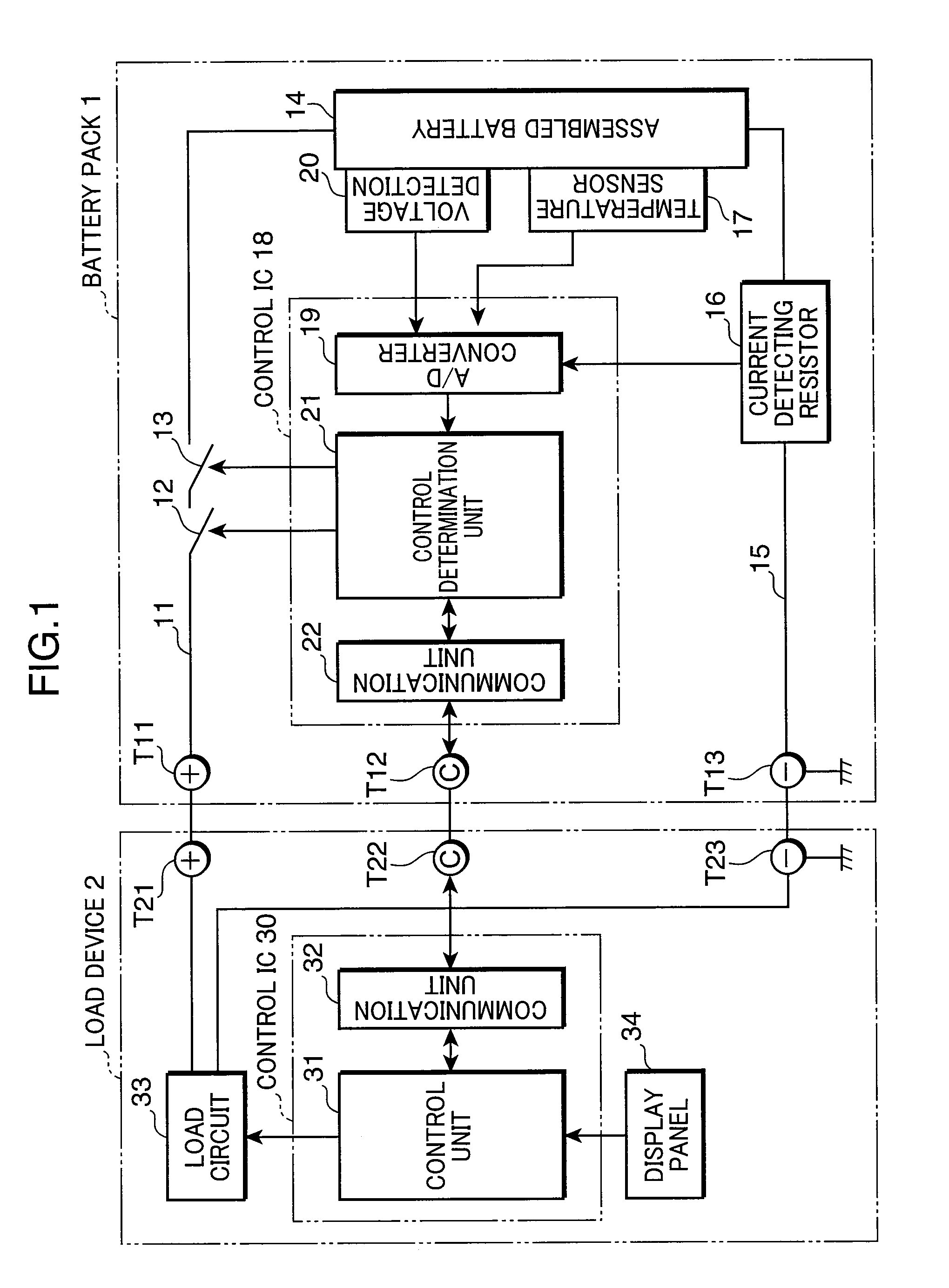
[0029]FIG. 1 is a block diagram showing an electronic structure of an electronic device system according to one embodiment of the present invention. In this electronic device system a battery pack 1 has a load device 2 supplied with power source from the battery pack 1, and the battery pack 1 is charged by a charger, which is not shown. When charging, the battery pack 1 is mounted on the load device 2 to charge the battery pack 1 via the load device 2. The battery pack 1 and the load device 2 are connected to each other by direct current high-side terminals T11, T21 for feeding power, communication signal terminals T12, T22, and GND terminals T13, T23 for power feeding and communication signals. The charger also is provided with the same three terminals.
[0030]In the battery pack 1, FET 12, 13 with different types of conductivity for charging and discharging are interposed in a direct current high-side charge / discharge path 11 extending from the terminal T11, and this charge / discharg...
PUM
 Abstract
Description
Claims
Application Information
 - R&D
- Intellectual Property
- Life Sciences
- Materials
- Tech Scout
- Unparalleled Data Quality
- Higher Quality Content
- 60% Fewer Hallucinations
Browse by: Latest US Patents, China's latest patents, Technical Efficacy Thesaurus, Application Domain, Technology Topic, Popular Technical Reports.
© 2025 PatSnap. All rights reserved.Legal|Privacy policy|Modern Slavery Act Transparency Statement|Sitemap|About US| Contact US: help@patsnap.com


