Method of Manufacture of an Energy Storage Device

a manufacturing method and energy storage technology, applied in the field of electrochemistry, can solve the problem of reducing the probability of stack cross-linking, and achieve the effect of improving the quality of the manufactured electrod

Inactive Publication Date: 2010-07-29
LYUBOMIRSKIY ALEXANDER +7
View PDF18 Cites 8 Cited by
  • Summary
  • Abstract
  • Description
  • Claims
  • Application Information

AI Technical Summary

Benefits of technology

[0012]The large sizes of the cations of tetrapropyl ammonium and tetrabutyl ammonium facilitate the formation of the polymer stacks disposed sufficiently far apart from each other, which reduces the probability of cross linking of the stacks. When the electrode is in use, the cations of the electrolyte used in an energy storage device freely move between the polymer stacks, resulting in an increase of the energy capacity and stability of operation of the energy storage device.
[0017]Deposition of a layer of the redox polymer can also be carried out with the simultaneous circulation of the electrolyte, which allows to improve the quality of the manufactured electrode.

Problems solved by technology

The large sizes of the cations of tetrapropyl ammonium and tetrabutyl ammonium facilitate the formation of the polymer stacks disposed sufficiently far apart from each other, which reduces the probability of cross linking of the stacks.

Method used


Image

  • Method of Manufacture of an Energy Storage Device
  • Method of Manufacture of an Energy Storage Device
  • Method of Manufacture of an Energy Storage Device

Examples


Embodiment Construction

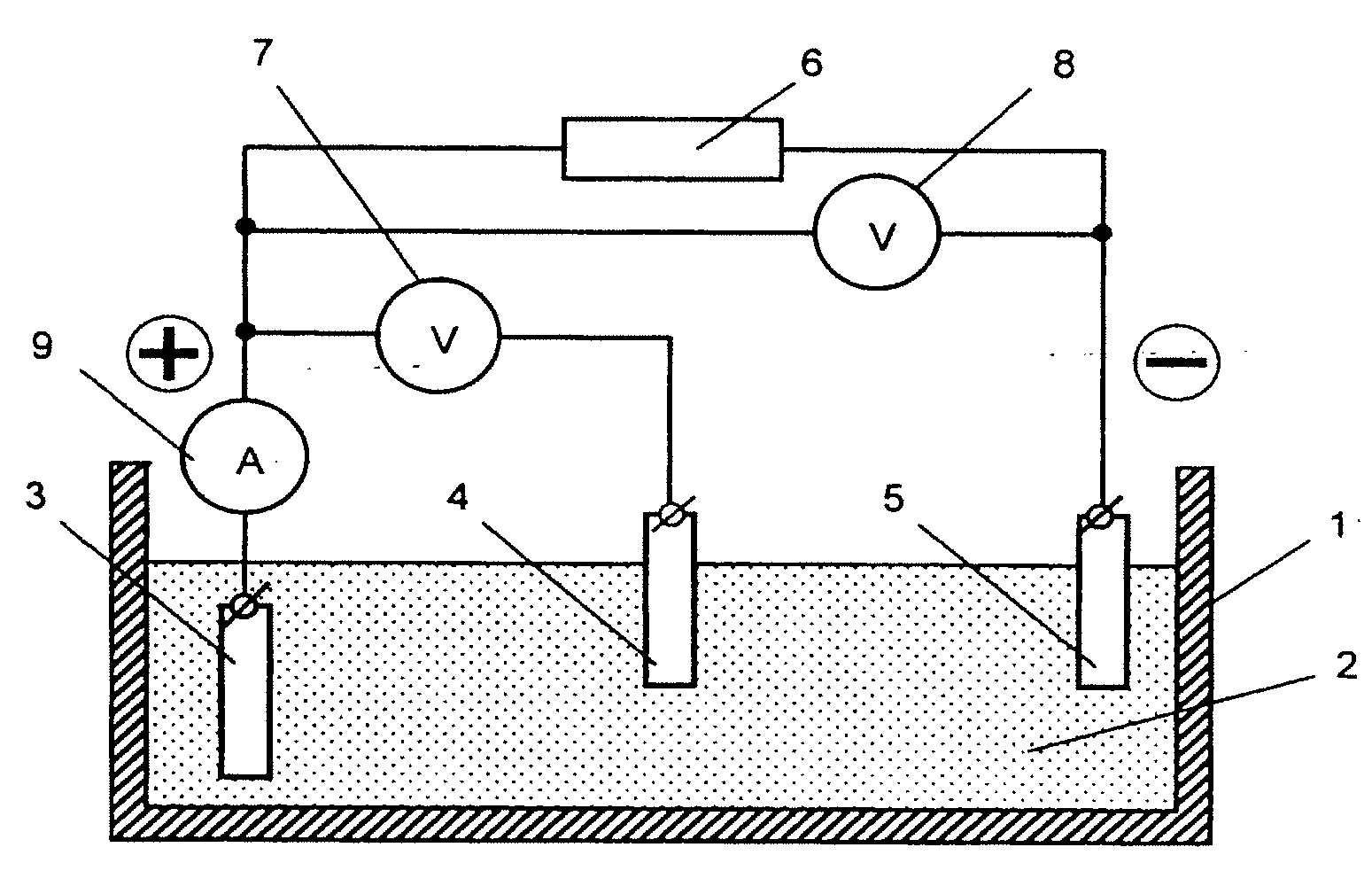
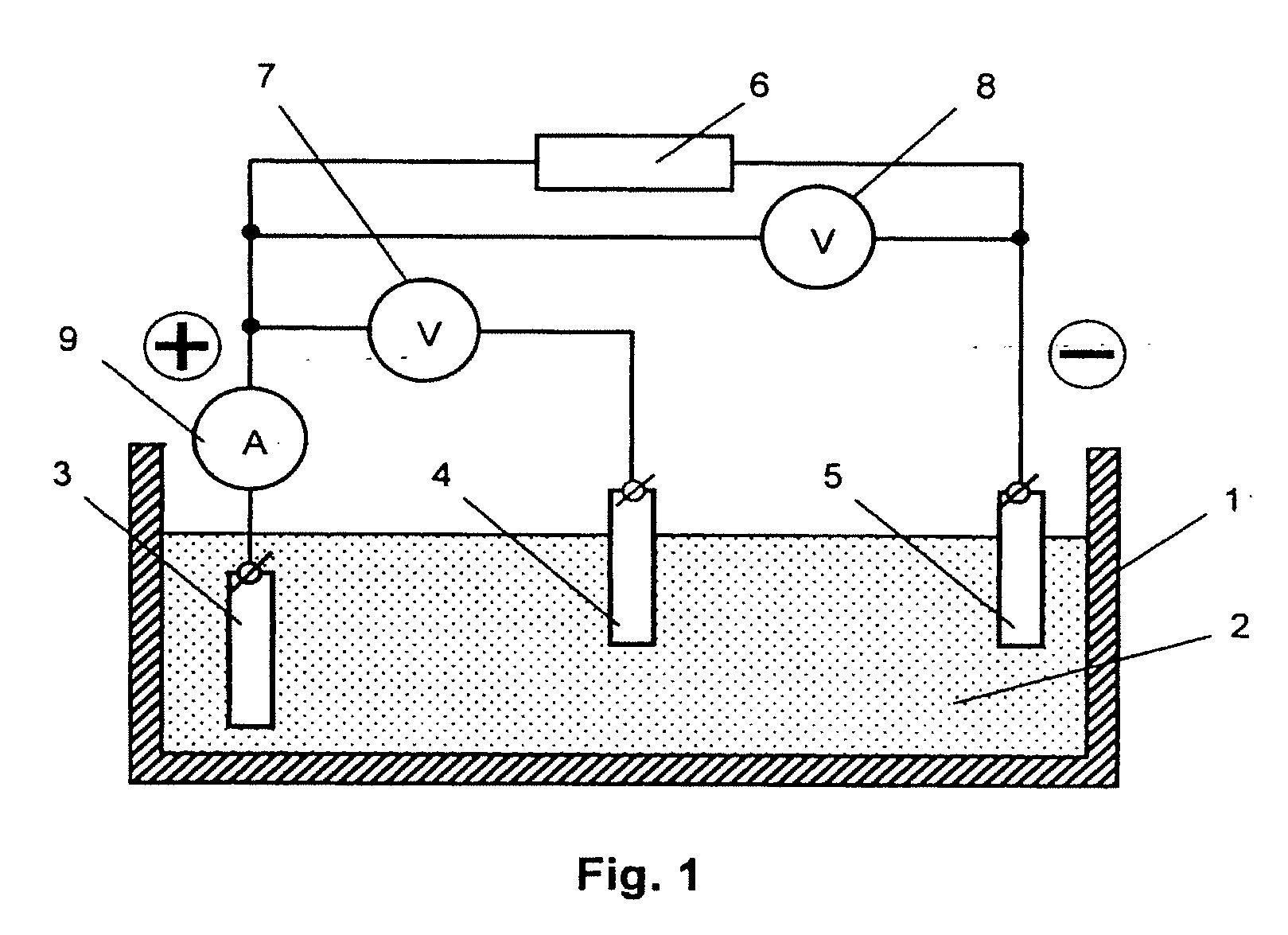
[0023]A schematic diagram of an apparatus for depositing the redox polymer layer onto a substrate of an electrode in accordance with the inventive method is shown in FIG. 1. The apparatus comprises the following components. Reservoir 1 is filled with electrolyte 2, into which conducting substrate 3, comparison electrode 4 (e.g. a chlorine-silver electrode), and counter electrode 5 are submerged. Substrate 3 is electrically connected to the positive pole of voltage source 6, while counter electrode 5 is connected to the negative pole of voltage source 6. Control instruments for measuring and monitoring the voltage between substrate 3 and counter electrode 5 (voltmeter 7), voltage between substrate 3 and comparison electrode 4 (voltmeter 8) and the intensity of current flowing in the circuit of substrate 3 (ampere meter 9) are connected according to the scheme shown in FIG. 1.

[0024]Electrolyte 2 can be prepared based on organic solvents of the acetonitrile, dimethyl ketone, or propyle...


PUM

PropertyMeasurementUnit
diameteraaaaaaaaaa
diameteraaaaaaaaaa
diameteraaaaaaaaaa

Abstract

A method of preparing an energy-storage device is disclosed, which involves deposition of a redox polymer of the poly-Me(R-Salen) type onto a conducting substrate by electrochemical polymerization to prepare an electrode for use in the energy-storage device. Polymerization occurs at a voltage applied between the substrate and a counter-electrode, both of which are submerged in an electrolyte. The electrolyte contains an organic solvent, compounds capable of dissolving in the solvent and forming electrochemically inactive ions at concentrations of no less than 0.01 mol / L within the range of potentials from −3.0 V to +1.5 V, and a metal complex polymer represented by the formula poly-[Me(R-Salen)] dissolved at a concentration of no less than 5×10⁻⁵ mol / L, wherein Me is a transition metal having at least two different degrees of oxidation, R is an electron-donating substituent, and Salen is a residue of bis(salicylaldehyde)-ethylenediamine. Deposition of the redox polymer occurs in an electrolyte in which the cations have a diameter that is larger than the diameter of the cations of the electrolyte employed in the energy-storage device for which the electrode is manufactured.

Description

RELATED APPLICATIONS[0001]This application is a continuation of U.S. patent application Ser. No. 11 / 100,036 filed on Apr. 6, 2005, which is a continuation of International (PCT) Application No. PCT / IB03 / 04410 filed on Oct. 7, 2003, which claims the benefit of U.S. Provisional Patent Application Serial No. 60 / 416,593 filed on Oct. 7, 2002, each of which is incorporated by reference herein in its entirety.FIELD OF THE INVENTION[0002]The invention relates to the field of electrochemistry. More specifically, the present invention relates to the methods of manufacture of electrodes that are chemically modified by a redox polymer for use, for example, in energy-storage devices (e.g. capacitors).BACKGROUND OF THE INVENTION[0003]The known methods of manufacture of electrodes with a polymer coating are mainly based on the method of chemical polarization [for example, U.S. Pat. No. 4,999,263 Mar. 12, 1991; U.S. Pat No. 6,533,918, Mar. 18, 2003; U.S. Pat. Appl. No 20020089807A1, Jul. 11, 2002]...

Claims


Application Information

Patent Timeline
Patent Type & Authority Applications(United States)
IPC IPC(8): H01G9/042C08F2/58B05D3/00H01G9/035H01G9/00H01G9/04H01G9/058H01M4/137H01M4/60H01M4/66
CPCH01G9/0032H01G9/0036H01G9/04H01M4/0438H01M4/0466H01M4/137Y02E60/122H01M4/66H01M4/663H01M4/667H01M4/668Y02E60/13H01G11/48H01M4/60Y02E60/10H01M4/04
Inventor LYUBOMIRSKIY, ALEXANDERPAVLOV, VALERIY VALENTINOVICHTIMONOV, ALEXANDER MIKHAILOVICHLOGVINOV, SERGEY ANATOLIJEVICHPIVUNOV, DMITRIY IVANOVICHVASILJEVA, SVETLANA VIKTOROVNASHKOLNIK, NIKKOGAN, SAM
Owner LYUBOMIRSKIY ALEXANDER
Why Eureka
Try Eureka