Method of strengthening tool material by super-deep penetration of reinforcing particles for manufacturing a composite tool material

a tool material and super-deep penetration technology, applied in the field of composite material manufacturing, can solve the problems of inconvenient production and use of carcinogenic materials, limited physical properties of tungsten carbide (wc) or cobalt alloy as cutting tools employed in mining industry, and relatively low resistance of wc, so as to achieve uniform structure and mechanical properties.

Inactive Publication Date: 2010-07-29
NANOTECH INDS +1
View PDF8 Cites 7 Cited by
  • Summary
  • Abstract
  • Description
  • Claims
  • Application Information

AI Technical Summary

Benefits of technology

[0017]It is an object of the invention to provide a homogeneously reinforced massive composite tool material based on high-speed steel (HSS), the matrix of which is reinforced with nano-and micro-structured fibers (<<elongated>> zones) formed by ceramic particles. It is a further object to provide the aforementioned massive composite tool material with a substantially uniform distribution of structure and mechanical properties over the entire length and cross-section of the treated body. It is another object to provide the aforementioned massive composi

Problems solved by technology

Generally, the use of tungsten carbide (WC) or cobalt (Co) alloys as materials for the cutting inserts of cutting tools employed in the mining industry is limited by physical properties of the tool per se as well as by relatively low resistance of the WC—Co-based cutting inserts to impacts and flexural loads.
Moreover, in Europe WC and Co alloys are regarded as carcinogenic materials unsuitable for production and use.
For example, in the mining industry, coating-reinforced cutting tool inserts cannot be efficiently used because the need for frequent change of such inserts significantly decreases efficiency of the cutting process and mining and impair operating conditions for workers.
For the last 70 years, cutting tools have been equipped with cutting inserts made predominantly from WC—Co alloys, which have low resistance to dynamic loads and are ecologically hazardous.
This, in turn, increases the protruding length of the insert and, eventually, leads to insert breakage under the effect of flexural loads and impacts.
Furthermore, the rapid cooling of cutting tools for the purpose of creating better operating conditions and for increasing cutting efficiency develops a network of cracks in the material of the hard alloy.
These cracks lead to cutting-tool breakage and to an increase in dynamic load on the equipment.
Contact with products of cutting-chip breakage is hazardous to the health of working personnel and therefore demands additional safety measures.
Physical and mechanical properties of known tool materials limit the design possibilities for development of new design tools and for saving energy consumed by cutting and mining processes.
This method, however, is not suitable for strengthening tool steel by converting it into a massive homogenously strengthened composite material (hereinafter referred as “massive composite material”) an

Method used


Image

  • Method of strengthening tool material by super-deep penetration of reinforcing particles for manufacturing a composite tool material
  • Method of strengthening tool material by super-deep penetration of reinforcing particles for manufacturing a composite tool material
  • Method of strengthening tool material by super-deep penetration of reinforcing particles for manufacturing a composite tool material

Examples


example 1

[0051]A specimen of an HSS type (6% W, 5% Mo) was treated according to the method of the invention with use of a jet of a working medium introduced into the end face of the specimen. Along its length, the jet had three portions similar to each other in velocity and density and was formed with instability in the lengthwise direction in the velocity range of 200 to 3000 m / sec and in the density range of 0.1 to 1.3 (with reference to the theoretical density of the working medium).

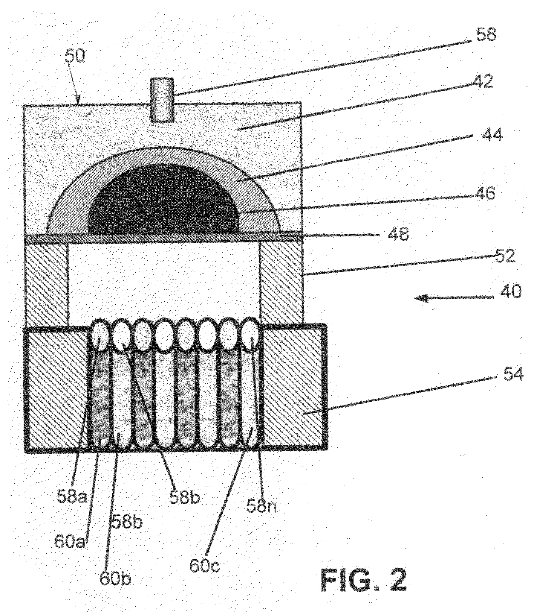
[0052]The specimen comprised a cylindrical steel body of about 40 mm in diameter and 100 mm in length and was mechanically treated to a smooth surface. The steel cylindrical specimen was installed vertically with a sliding fit in the opening of the container 54 (FIG. 2) and below the adjusting support 52 of the type described above with reference to FIG. 2. The support was adjusted to dimensions that after compression of the shell 44 of the cartridge 50 with the energy of the explosion could provide and guide ...

example 2

[0059]In this experiment, the accelerator used was the same as that in Example 1. The material of the blank steel and the dimensions of the blanks also were the same as those in Example 1. Upon completion of super-deep penetration with use of the working-medium jet in accordance with the scheme shown in FIG. 2, the treated blanks were subjected to the same mechanical treatment as in the preceding example. Example 2 differs from Example 1 in that the working-medium composition was prepared on the basis of ceramic powder of silicon carbide (shown in Table 3).

TABLE 3Compositions of Working-Medium MixturesTestNo.Composition1SiC (3-250 μm) 50% + Ni (1-100 μm) 40% +Al2O3 (20-50 μm) 10%2SiC (3-250 μm) 100%3SiC (3-250 μm) 10% + Ni (1-100 μm) 20% +Al2O3 (20-50 μm) 70%4SiC (3-250 μm) 50% + Ni (1-100 μm) 50%5SiC (3-250 μm) 10% + Ni (1-100 μm) 20% +TiB2 (40-50 μm) 70%

As shown in Table 4 below, deviation from the optimal composition essentially changed the mechanical properties of the obtained c...

example 3

[0062]Specimens of the composite tool material were manufactured and tested in the same manner as in Example 1 with regard to mechanical properties. The main distinction of Example 3 is that the initial size of the working medium particles differed from those used in Example 1.

[0063]The composites used are shown in Table 5, and the results of mechanical tests of the obtained composite materials are shown in Table 6.

TABLE 5Compositions of Working-Medium MixturesUsed for Treating Steel BlanksTestNo.Composition1TiCN (1-100 μm) 60% + Ni (1-100 μm) 30% +Si3N4 (0-60 μm) 10%2TiCN (3-14 μm) 60% + Ni (0-20 μm) 30% +Si3N4 (40-50 μm) 10%3TiCN (100-160 μm) 60% + Ni (120-200 μm) 30% +Si3N4 (3-14 μm) 10%4TiCN (120-160 μm) 60% + Ni (120-200 μm) 40%

TABLE 6Mechanical Properties of Composite Tool MaterialAfter Treatment by Method of Invention with Use of Compositionsin Table 5Strength with Referenceto Untreated SteelTestCompositionResistanceNo.No.to WearFlexural StrengthImpact Strength1—111211.31.151...


PUM

PropertyMeasurementUnit
Temperatureaaaaaaaaaa
Lengthaaaaaaaaaa
Lengthaaaaaaaaaa

Abstract

1. A method of strengthening the matrix of a high-speed steel for forming a composite tool material by super-deep penetration of reinforcing particles into and through the matrix of the tool material. The particles interact with the matrix in the form of a high-speed jet generated and energized by an explosion of an explosive material that contains the premixed powdered components of the working medium composed of particles of a hard material and ductile metal, and if necessary, with an addition of a process liquid. The particles of the working medium material have dimensions ranging from 1 to 100 μm. The jet has a pulsating nature with the velocity in the range of 200 to 600 m/sec and a temperature in the range 100 to 2000° C. As a result of strengthening, the steel matrix is reinforced by elongated zones of the working material particles which are oriented in the direction of the jet and occupy less than 1 vol. % of the matrix material, while less than 10 vol. % is occupied by the zones of the matrix restructured as a result of interaction with the particles of the super-high velocity jet.

Description

FIELD OF THE INVENTION[0001]The invention relates to the process of manufacturing composite materials on the basis of a matrix of a tool material, in particular, high-speed steel (HSS) intended for production of cutting tools used in metal cutting and mining industries. More specifically, the invention relates to a method of manufacturing high-speed steel strengthened by super-deep penetration of ceramic and other hard particles. In particular, the invention concerns a method for converting HSS billets into massive composite materials for manufacturing cutting-tool inserts. Such materials can also be used for manufacturing cutting tools the material of which is reinforced with fibrous elongated alloying inclusions and with restructured zones of the material matrix, which, however, do not change the basic properties of the matrix material.BACKGROUND OF THE INVENTION[0002]Generally, the use of tungsten carbide (WC) or cobalt (Co) alloys as materials for the cutting inserts of cutting ...

Claims


Application Information

Patent Timeline
IPC IPC(8): B05D1/12
CPCC22C1/002C21D9/22C22C1/11
Inventor USHERENKO, SERGEY
Owner NANOTECH INDS
Why Eureka
Try Eureka