Low loss joint for superconducting wire

a superconducting wire and low-loss technology, applied in the direction of superconducting magnets/coils, magnetic bodies, connection contact material, etc., can solve the problems of affecting the desirability of mri superconductor, affecting the field to an unacceptable level, and joining the ends of successive wire lengths

Active Publication Date: 2010-07-29
HYPER TECH RES
View PDF17 Cites 58 Cited by
  • Summary
  • Abstract
  • Description
  • Claims
  • Application Information

AI Technical Summary

Problems solved by technology

Despite all the benefits offered by NbTi wire, it has a single weakness that greatly affects its desirability as a MRI superconductor.
The charging leads are removed leaving the superconducting magnet with a persistent magnetic field, which will remain until the low electrical resistance joints and inherent low resistance of the superconducting wire in the magnet dissipate the field to an unacceptable level.
However, joining the ends of successive wire lengths presents several issues.
This leaves the Nb, Fe, or other sheath materials and the MgB2, which has a low strain tolerance vulnerable to fracture when compressed against its neighbor.
If mechanical means are done improperly, cracks can occur thereby breaking the reacted MgB2 and losing electrical continuity, while chemical means may etch away the MgB2 faster than it does Nb, a refractory metal.
A key problem to address is the manufacturability of a persistent joint.
These disclosures fail in achieving the best method for forming the aforementioned superconducting bridge between the two ends of previously reacted MgB2 wire.
This less than desirable result stems from the fact tha

Method used


Image

  • Low loss joint for superconducting wire
  • Low loss joint for superconducting wire
  • Low loss joint for superconducting wire

Examples


Embodiment Construction

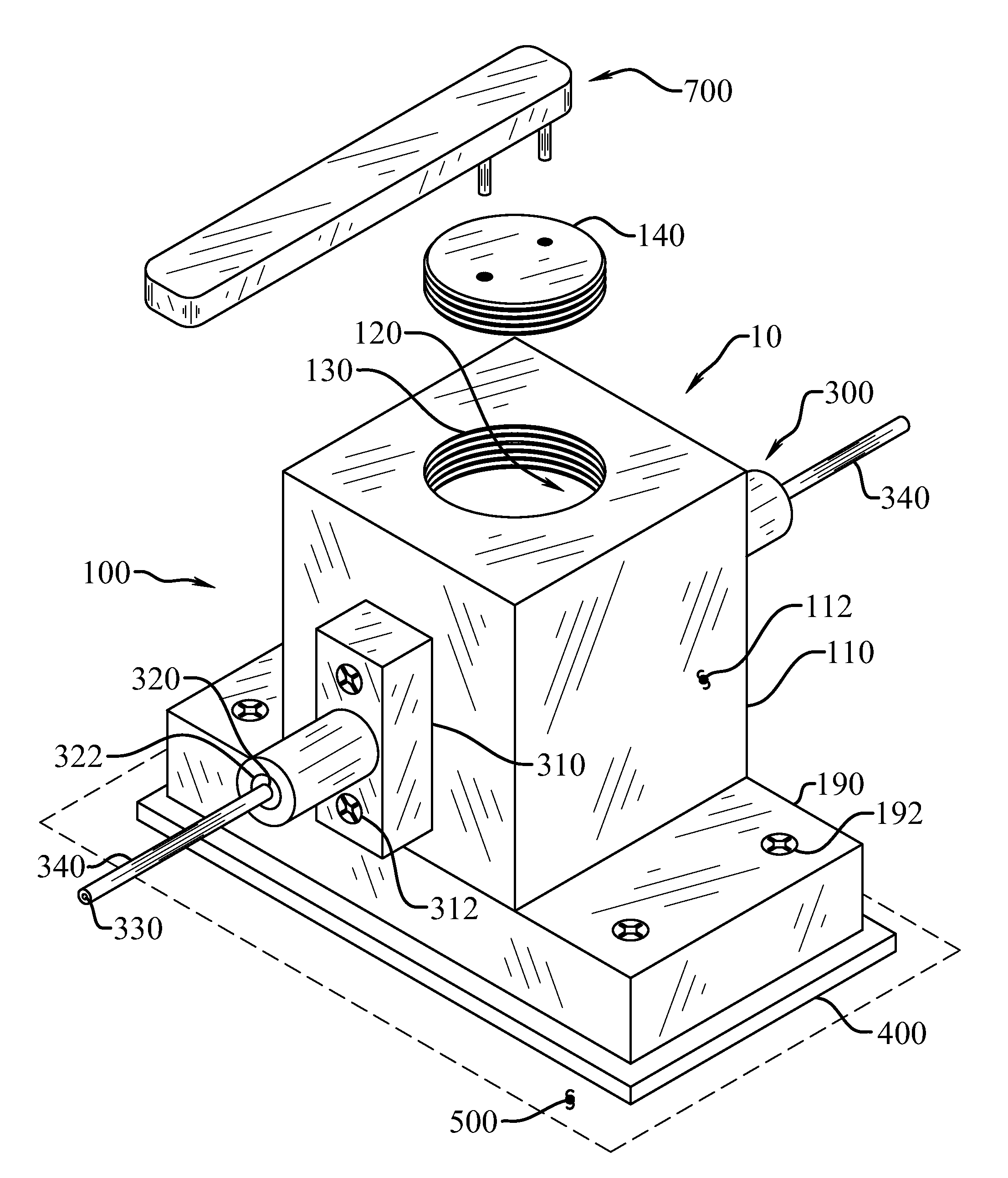
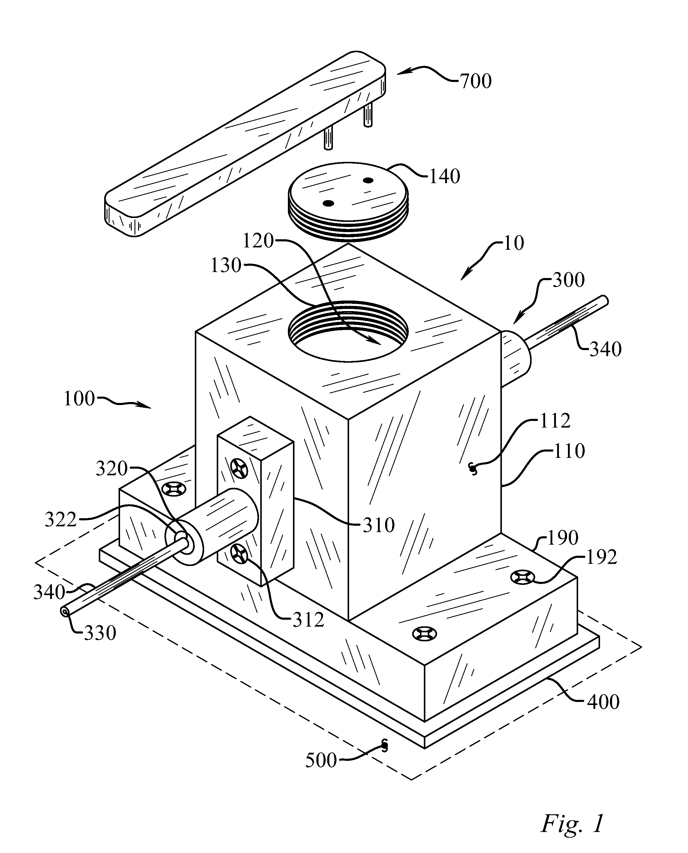
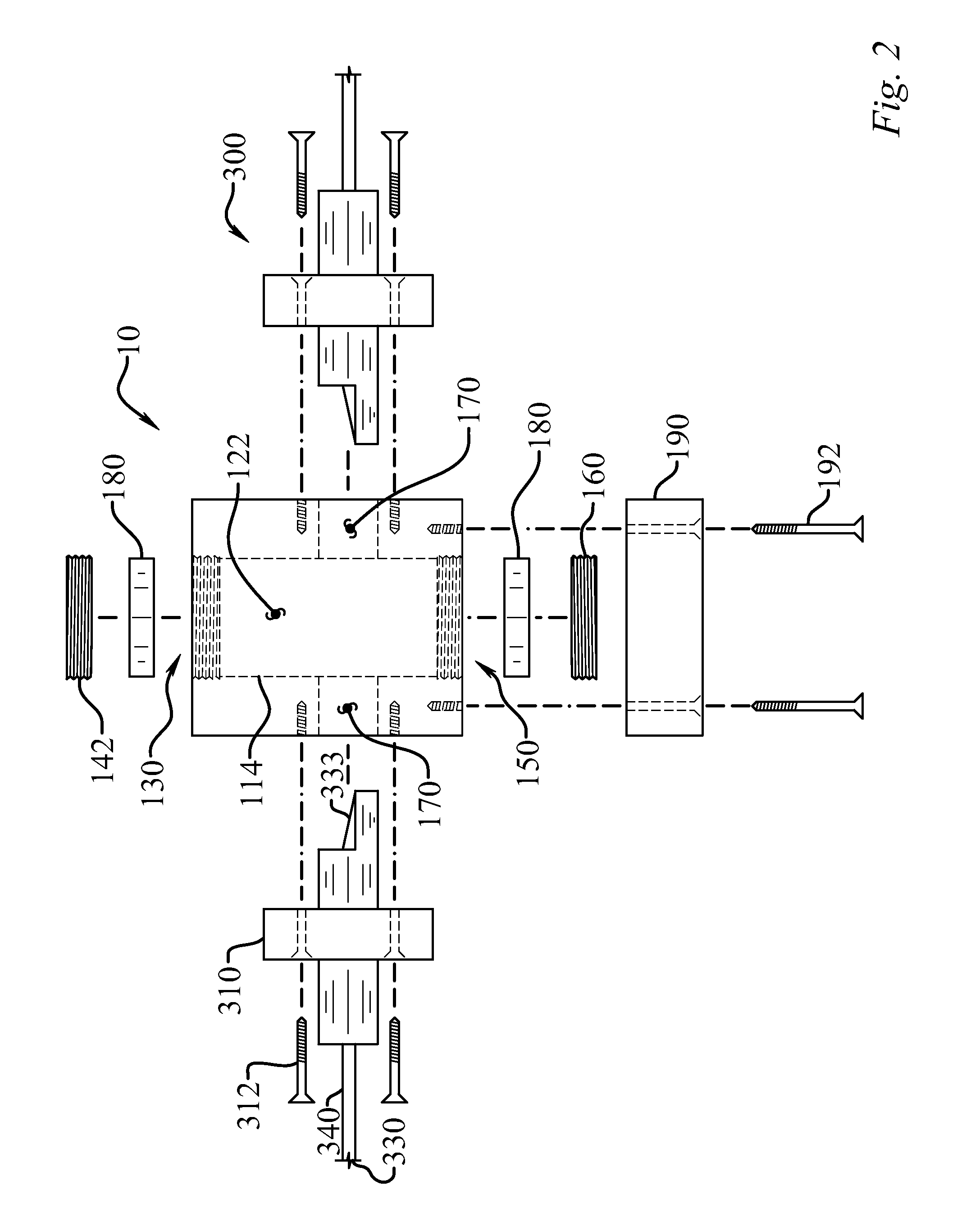
[0041]The low loss joint (10) for MgB2 superconducting wire (330) and method of forming the enables a significant advance in the state of the art. The preferred embodiments of the device accomplish this by new and novel arrangements of elements and methods that are configured in unique and novel ways and which demonstrate previously unavailable but preferred and desirable capabilities. The detailed description set forth below in connection with the drawings is intended merely as a description of the present embodiments of the device, and is not intended to represent the only form in which the present device may be constructed or utilized. The description sets forth the designs, functions, means, and methods of implementing the device in connection with the illustrated embodiments. It is to be understood, however, that the same or equivalent functions and features may be accomplished by different embodiments that are also intended to be encompassed within the spirit and scope of the ...


PUM

PropertyMeasurementUnit
Temperatureaaaaaaaaaa
Fractionaaaaaaaaaa

Abstract

A device and method for making a persistent joint allowing end terminations of superconducting MgB2 wire to be joined with a superconducting bridge. Superconducting electromagnetic coils may be joined in series or joining of coil assemblies to current sources and the two ends of a persistent switch. The device includes wire filaments with end preparation exposing reacted MgB2, inserted into a block and surrounded with Mg+B and/or MgB2 in powder, solid, slurry or sol-gel form and subsequently reacted to establish a bridge of superconducting MgB2 electrically connecting the superconducting MgB2 wires. Autonomous operation of the superconducting background magnet coils in magnetic resonance imaging (MRI) and nuclear magnetic resonance (NMR) devices are allowed, or similar devices where autonomous operation of an MgB2 based superconducting magnet is required. The low resistant joint will also be beneficial for other superconducting applications such as fault current limiters, motors, generators, etc.

Description

CROSS-REFERENCE TO RELATED APPLICATIONS[0001]This application claims priority to U.S. Patent Application No. 61 / 148,111, filed Jan. 29, 2009, all of which is incorporated by reference as if completely written herein.STATEMENT REGARDING FEDERALLY SPONSORED RESEARCH OR DEVELOPMENT[0002]Not ApplicableBACKGROUND OF THE INVENTION[0003]Superconducting wires have enabled high current density in a conductor, which has enabled high field magnets. This in turn has enabled magnetic resonance imaging (MRI) of increasing resolution and clarity, a goal for all medical diagnosis. Traditionally, the wire of choice has been niobium titanium (NbTi), developed several years ago for the intended use of achieving high magnetic fields in high energy physics applications. The emergence of MRI has since dominated the market for this product for a number of reasons. First, NbTi is ductile and can undergo considerable strain (˜1%) before failing, thereby greatly simplifying manufacturing. Second, successive ...

Claims


Application Information

Patent Timeline
IPC IPC(8): H01L39/02H01L39/24
CPCH01L39/02H01L39/2487Y10T29/49014Y10S505/925Y10S505/926H01R4/68H10N60/80H10N60/0856
Inventor DOLL, DAVID W.TOMSIC, MICHAEL J.
Owner HYPER TECH RES
Why Eureka
Try Eureka