Secondary position feedback control of a robot

a robot and feedback control technology, applied in the direction of electric programme control, program control, instruments, etc., can solve the problems of increasing the difficulty of pure secondary encoder position control with primary encoder velocity and torque control, and the mechanical unit's compliance error is the greatest source of error, so as to achieve the effect of maintaining the capability of higher speed motion and removing the complexity of handling interaction

Active Publication Date: 2010-07-29
FANUC ROBOTICS NORTH AMERICA
View PDF11 Cites 46 Cited by
  • Summary
  • Abstract
  • Description
  • Claims
  • Application Information

AI Technical Summary

Benefits of technology

[0017]The advantage of this system is that it removes the complexity of handling interaction at the level of a single position control loop, while maintaining the capability of higher speed motion with dynamic position maintained by the secondary encoders even for axes with interaction.

Problems solved by technology

Typically, after initial joint angle calibration, the greatest source of error is compliance of the mechanical unit under loading.
The greatest amount of this compliance error occurs in the gear train of the robot.
The pure secondary encoder position control with primary encoder velocity and torque control becomes difficult in the case of interaction between robot axes, such as an inline, three roll wrist.
The control loop would need information from other axes during the low level control; this is not always feasible.
Also it may not be convenient to use a single control loop at the DSP (Digital Signal Processor) level for the case of advanced calibration techniques that are required for the secondary encoder.
Using the secondary encoder as a measurement system does not provide the response required for more than low speed and stationary motion.
Re-orientation or higher speed motion cannot be achieved without integration of the secondary encoders to a closed loop control system.
However, this control does not combine both position control by primary encoders and position control by secondary encoders.
The pure secondary encoder position control with primary encoder velocity and torque control becomes difficult in the case of interaction between robot axes, such as an inline, three roll wrist.
The control loop would need information from other axes during the low level control; this is not always feasible.
Using the secondary encoder as a measurement system does not provide the response required for more than low speed and stationary motion.
Re-orientation or higher speed motion cannot be achieved without integration of the secondary encoders to a closed loop control system.

Method used


Image

  • Secondary position feedback control of a robot
  • Secondary position feedback control of a robot
  • Secondary position feedback control of a robot

Examples


Embodiment Construction

[0027]The following detailed description and appended drawings describe and illustrate various exemplary embodiments of the invention. The description and drawings serve to enable one skilled in the art to make and use the invention, and are not intended to limit the scope of the invention in any manner. In respect of the methods disclosed, the steps presented are exemplary in nature, and thus, the order of the steps is not necessary or critical.

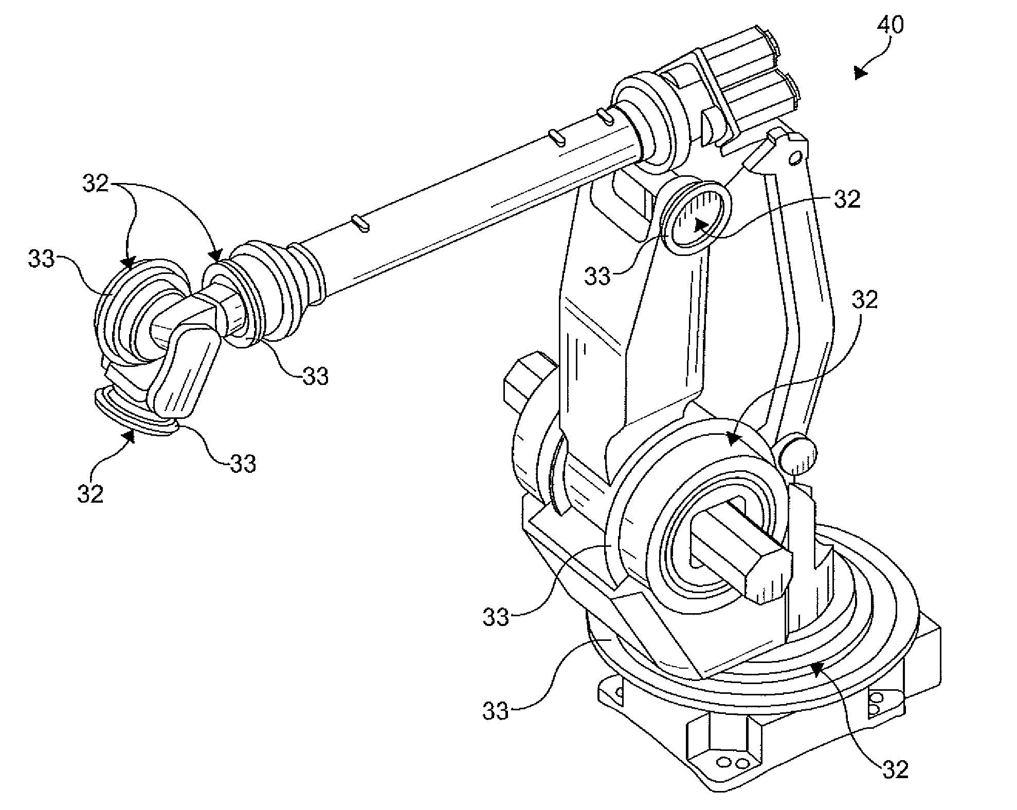
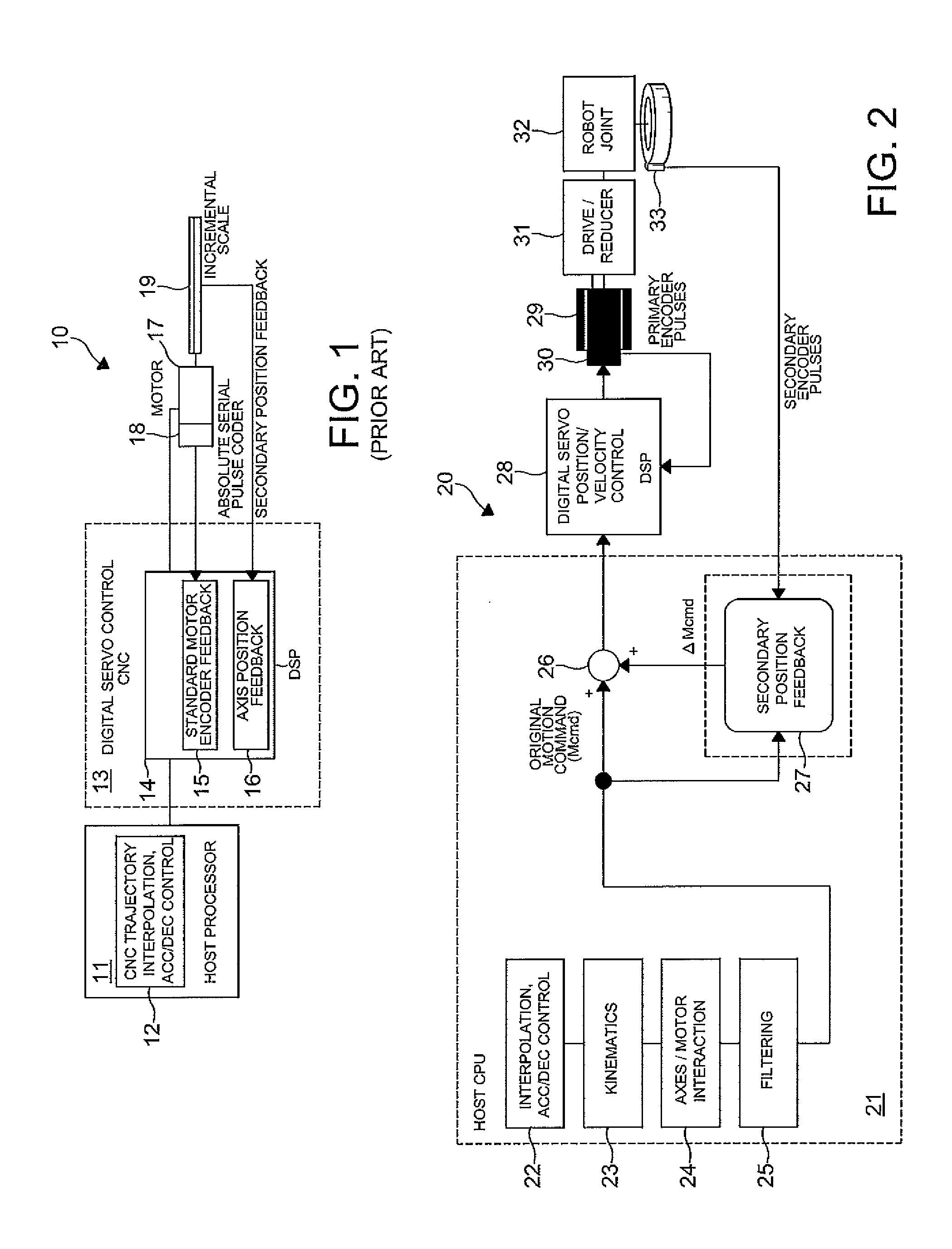
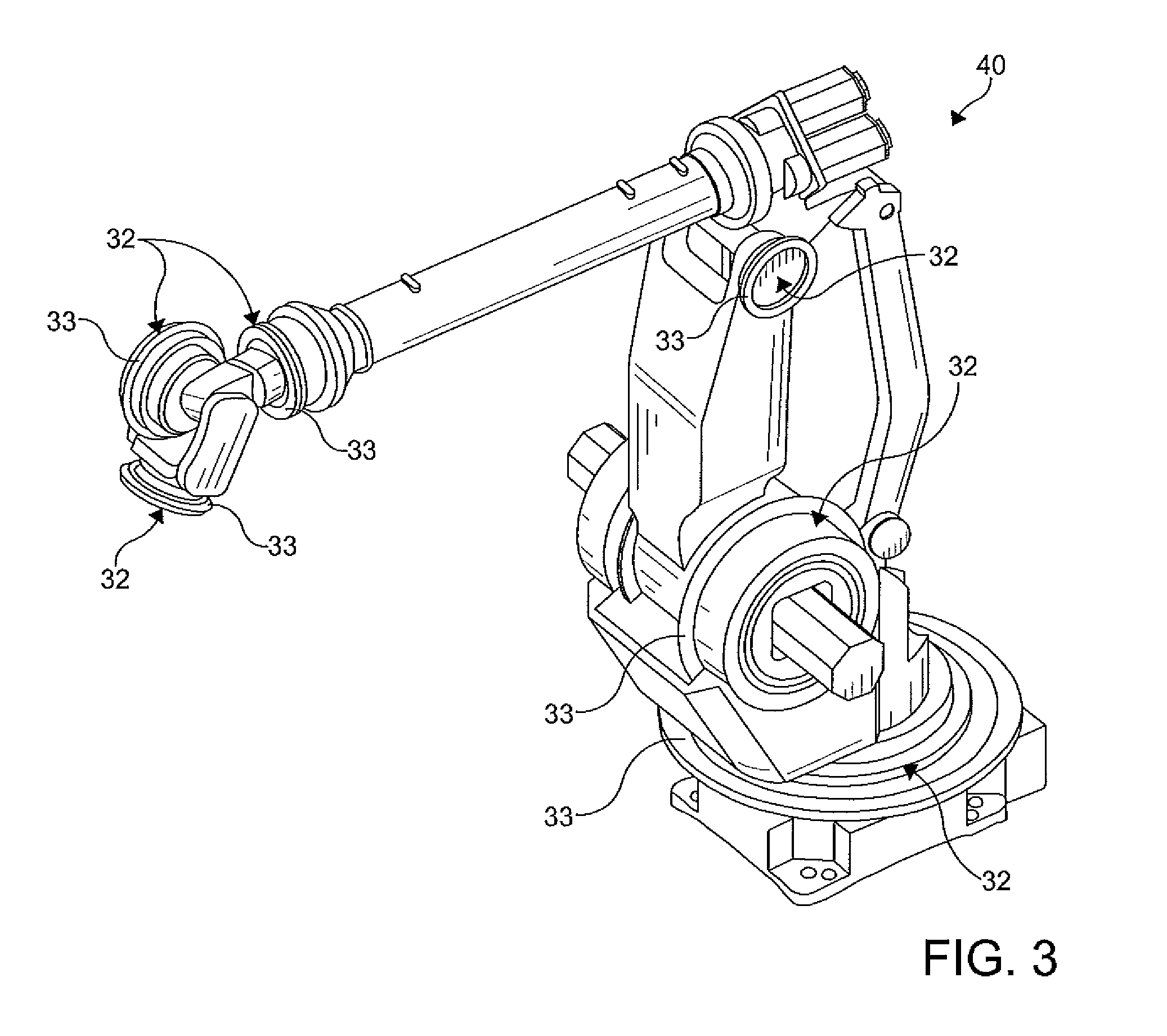
[0028]There is shown in FIG. 1 a schematic block diagram of a CNC controller 10 according to the prior art. A host processor 11 includes a CNC trajectory interpolation acceleration / deceleration control 12 connected to a digital servo control 13. The control 13 includes a DSP 14 with a standard motor encoder feedback circuit 15 and an axis position feedback circuit 16. In response to the control signal from the host processor 11, the DSP 14 generates a control signal to a robot motor 17. An absolute serial pulse coder 18 connected to the moto...


PUM


Abstract

A method of and apparatus for achieving dynamic robot accuracy includes a control system utilizing a dual position loop control. An outer position loop uses secondary encoders on the output side of the gear train of a robot joint axis, while the inner position loop uses the primary encoder attached to the motor. Both single and dual loop control can be used on the same robot and tooling axes.

Description

CROSS-REFERENCE TO RELATED APPLICATION[0001]This application claims the benefit of U.S. Provisional Patent Application No. 61 / 147,484 filed on Jan. 27, 2009, hereby incorporated herein by reference in its entirety.FIELD OF THE INVENTION[0002]This invention relates to a method of achieving dynamic robot accuracy utilizing a novel control approach. A control system uses a dual position loop control; the outer position loop uses secondary encoders on the output side of the gear train of a robot joint axis, while the inner position loop uses the primary encoder attached to the motor. Both single and dual loop control can be used on the same robot and tooling axes.BACKGROUND OF THE INVENTION[0003]This invention relates to highly accurate robots. Typically, after initial joint angle calibration, the greatest source of error is compliance of the mechanical unit under loading. The greatest amount of this compliance error occurs in the gear train of the robot.[0004]It has been recognized for...

Claims


Application Information

Patent Timeline
Patent Type & Authority Applications(United States)
IPC IPC(8): G05B19/18
CPCG05B2219/37297G05B19/404
Inventor TSAI, JASONWONG, ERICTAO, JIANMINGMCGEE, H. DEANAKEEL, HADI
Owner FANUC ROBOTICS NORTH AMERICA
Why Eureka
Try Eureka