
Method for producing a fuselage airframe of an aircraft

a technology for fuselage airframes and aircraft, which is applied in the direction of manufacturing tools, transportation and packaging, and other domestic objects, can solve the problem of no opportunity for tolerance compensation, and achieve the effect of avoiding loss of strength and avoiding impairment of layer structur

Active Publication Date: 2010-08-05
AIRBUS OPERATIONS GMBH
View PDF7 Cites 7 Cited by
  • Summary
  • Abstract
  • Description
  • Claims
  • Application Information

AI Technical Summary

Benefits of technology

[0018]The aluminium shell segments are preferably welded together by the friction stir welding process to achieve a high quality of the longitudinal seam, the mechanical characteristics of which are comparable with those of the solid material. Alternatively, the fuselage section can also be formed with sheets of Glare®, i.e. a laminar layer construction of alternatingly full-surface bonded thin aluminium alloy sheets and glass fibre reinforced plastics material layers. In this case, the longitudinal seam is formed by riveting, screwing or bonding in order to restrict the thermal strain on the Glare®. In exceptional cases, if the Glare® sheets are provided with special connection regions, a direct join is possible by thermal joining processes and in particular by friction stir welding. A combination of conventional aluminium alloy sheets with Glare® sheets is quite possible. If the metal construction method is combined with the CFRP construction method (hybrid construction method), particular attention should be paid to corrosion problems in the contact region between the aluminium materials and the composite material.
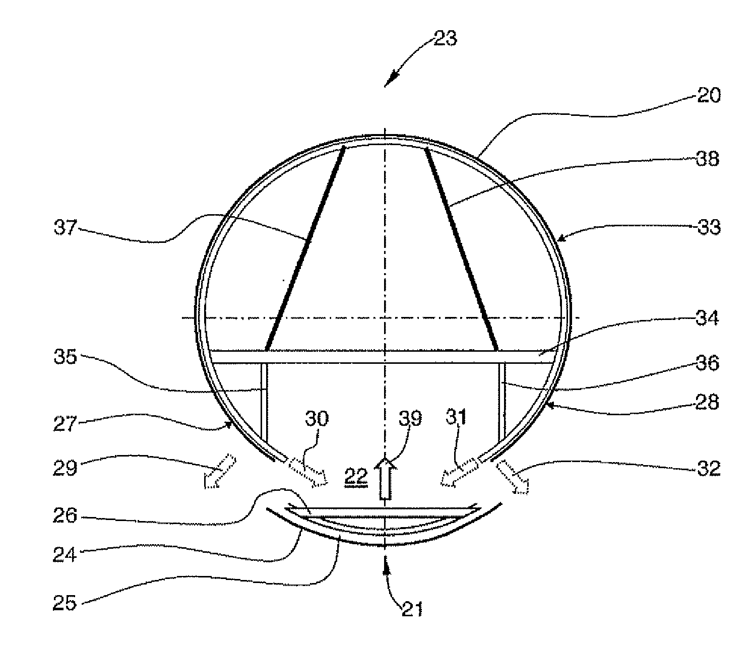
[0022]The outer skin segment is then joined to a fuselage section which is already prefabricated, which is usually effected by pushing the fuselage section to be joined onto so-called transverse butt straps which are arranged on the prefabricated fuselage section. The outer skin segment is always joined starting from the upper side on both sides running downwards with the formation of a partial transverse seam in order to successively work out or push out downwards on both sides possible “undulations or foldings” resulting due to tolerance variations of the still flexible outer skin segment. The continuous longitudinal opening in the region of the outer skin segment allows a tolerance compensation by slight widening or compression of the two sides of the outer skin segment which is still flexible at this stage. Thereafter, a preferably fully prefabricated lower shell is positioned and aligned in the underside longitudinal opening in the outer skin segment, as a result of which the outer skin segment is completed to form an outer skin which is closed over the periphery. At this time, the lower shell is already provided with all the stringer profiles and annular former segments.
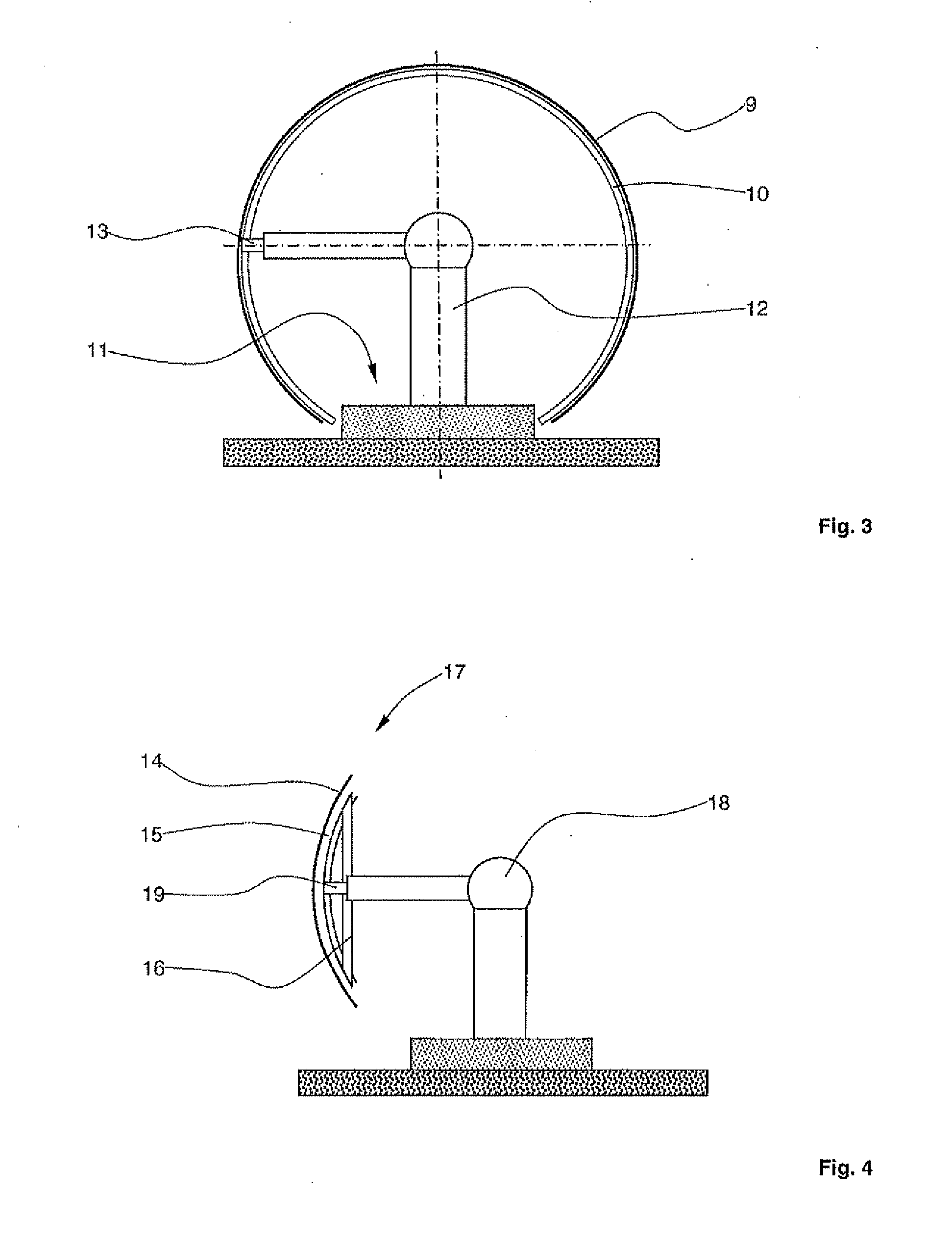
[0026]The open construction method described here with a continuous longitudinal opening greatly facilitates the removal of the winding core during the production of a wound outer skin segment in contrast to the production of a completely closed section in the winding process, as a result of which it is possible to produce relatively long cylindrical sections in the winding process.
[0029]If the outer skin segment and / or the lower shell is formed at least in regions with Glare® sheets, the joining procedure can then only be carried out by known welding processes if the Glare® sheets have thermally weldable joining regions in order to avoid impairment to the layer structure in the Glare® by the effect of heat and to avoid loss of strength caused thereby.

Problems solved by technology

Such a possibility of tolerance compensation is necessary, since the fuselage sections which are to be joined together have large spatial dimensions and, due to unavoidable manufacturing tolerances, only have exactly the same diameter in exceptional cases.
However, in the case of these rigid fuselage sections, there is no opportunity for tolerance compensation.

Method used


Image

  • Method for producing a fuselage airframe of an aircraft
  • Method for producing a fuselage airframe of an aircraft
  • Method for producing a fuselage airframe of an aircraft

Examples


Embodiment Construction

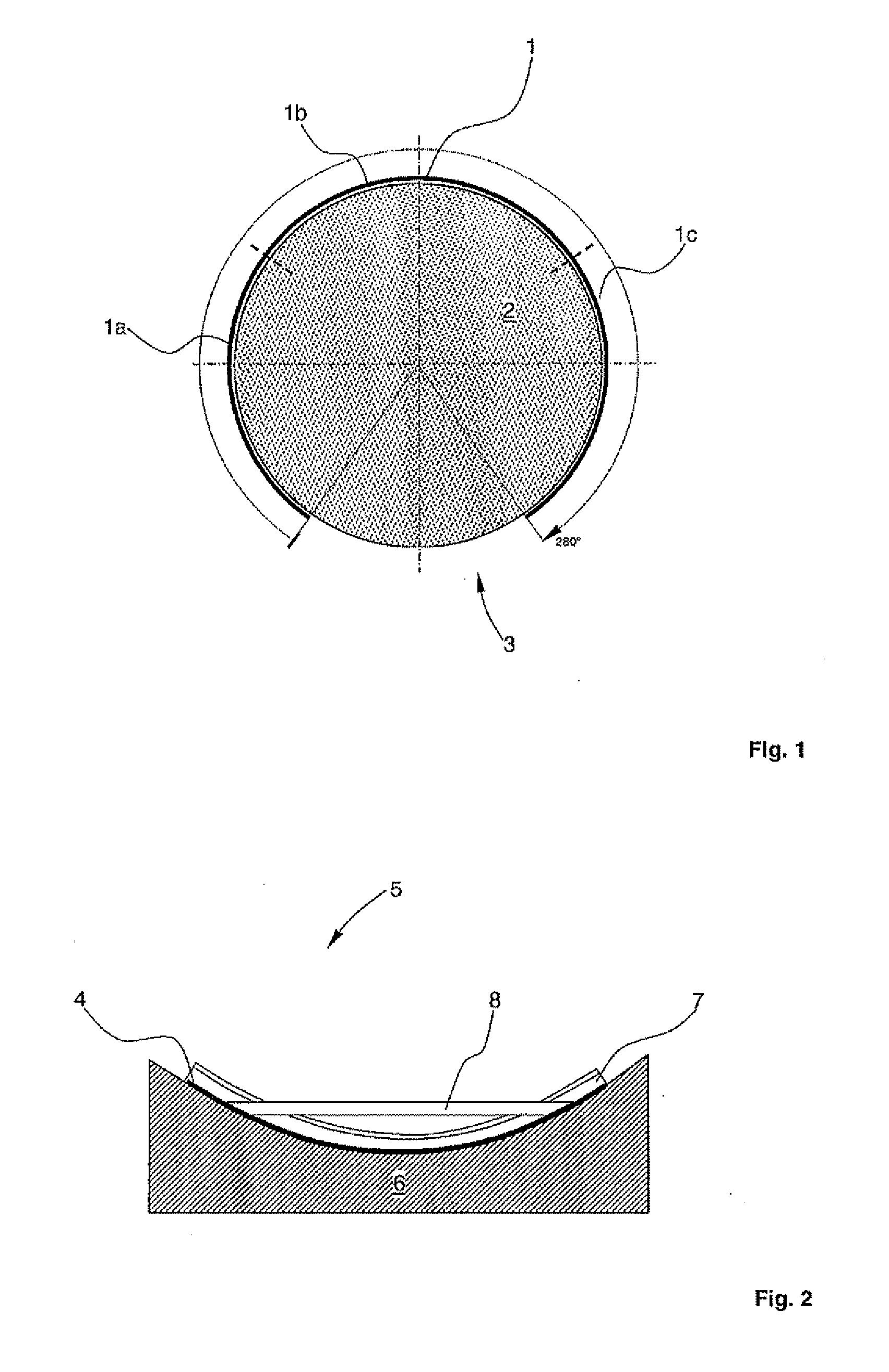
[0038]FIG. 1 is a schematised cross-sectional view through an outer skin segment 1 formed with a fibre reinforced plastics material.

[0039]In a first step, the outer skin segment 1 is prefabricated with a fibre reinforced plastics material, in particular with a carbon fibre reinforced epoxy resin, for example on a winding core 2 by known deposition processes or winding processes. During this winding process, the stringer profiles which are not shown in FIG. 1 and which also run in the longitudinal direction of the outer skin segment 1, i.e. vertically to the plane of the drawing, are also formed integrally with the outer skin segment. To compensate tolerances, the outer skin sheath 1 has on its lower side a continuous longitudinal opening 3 (longitudinal slot) which runs vertically to the plane of the drawing. A cross-sectional surface (not shown in FIG. 1) of the outer skin segment 1 preferably forms a pitch circle of approximately 280° or has an aperture angle of 80°. Other apertur...


PUM

PropertyMeasurementUnit
Angleaaaaaaaaaa

Abstract

Disclosed is a method for producing a fuselage of an aircraft, wherein several fuselage sections that are arranged one behind another are joined together, comprises the following steps:a) production of an outer skin segment, the outer skin segment having on the underside a continuous longitudinal opening,b) widening the outer skin segment in order to introduce at least one floor frame,c) joining the outer skin segments to a rigid fuselage section which is already present, with the formation of a partial transverse seam,d) positioning a prefabricated lower shell in the longitudinal opening, in order to close the outer skin segment on the peripheral side,e) completing the partial transverse seam to form a transverse seam and joining the lower shell together with the outer skin segment with the formation of at least two longitudinal seams, andf) joining the floor frame together with the outer skin segment.

Description

CROSS-REFERENCE TO RELATED APPLICATIONS[0001]This application is a continuation of PCT International Application No. PCT / EP2008 / 057345 filed Jun. 12, 2008, which claims the benefit of U.S. Provisional Application No. 60 / 994,279, filed Sep. 18, 2007 and German Patent Application No. 10 2007 044 387.2, filed Sep. 18, 2007, the entire disclosures of which are herein incorporated by reference.FIELD OF THE INVENTION[0002]The invention relates to a method for producing a fuselage airframe of an aircraft, in which method a plurality of fuselage sections positioned in tandem are joined together.[0003]Nowadays, fuselage sections for aircraft are frequently still produced in the tried and tested shell construction method using aluminium alloy sheets. Depending on the type of aircraft and the required fuselage diameter, a fuselage section is formed with from four to eight shell segments which are usually joined together by riveting to form a complete fuselage section. To form the complete fuse...

Claims


Application Information

Patent Timeline
IPC IPC(8): B21D53/88
CPCB64C1/068B64C2001/0072B64F5/0009Y10T29/49947Y10T29/49622Y10T29/49956Y10T29/49616Y02T50/433B64F5/10Y02T50/40
Inventor STEPHAN, ANDREAS
Owner AIRBUS OPERATIONS GMBH
Learn More