Humidity sensor based on progressive corrosion of exposed material
- Summary
- Abstract
- Description
- Claims
- Application Information
AI Technical Summary
Benefits of technology
Problems solved by technology
Method used
Image
Examples
Embodiment Construction
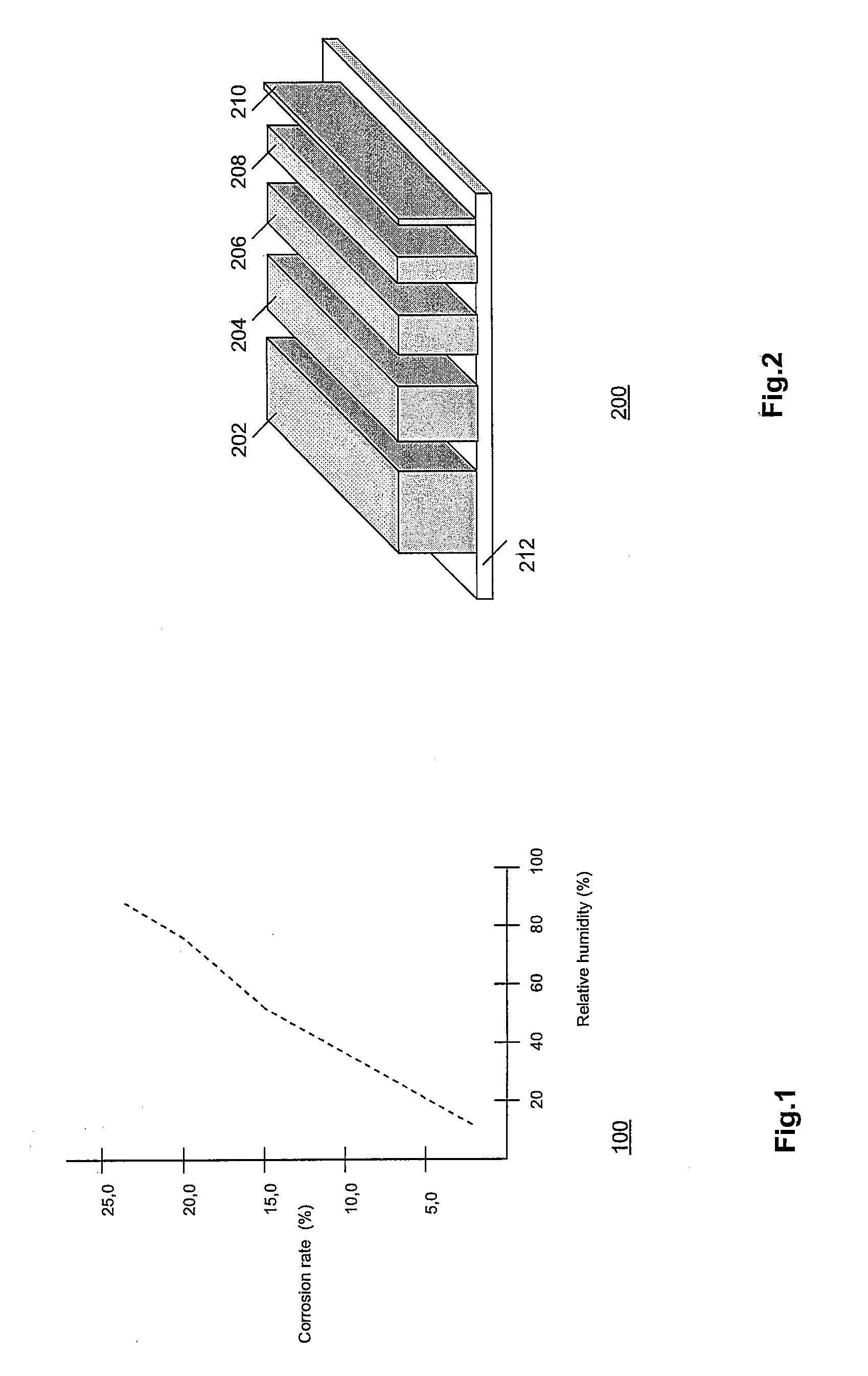
[0028]FIG. 1 is a diagram 100 showing the relationship between corrosion rate (in percentages) and relative humidity (in percentages), measured for a temperature between, say, 20°-30° C. The diagram is based on the publication of Lin and Zhang mentioned above. The dependence is roughly linear over the range of relative humidity.
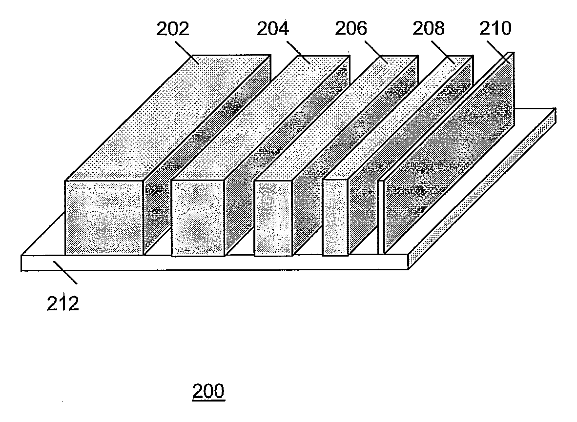
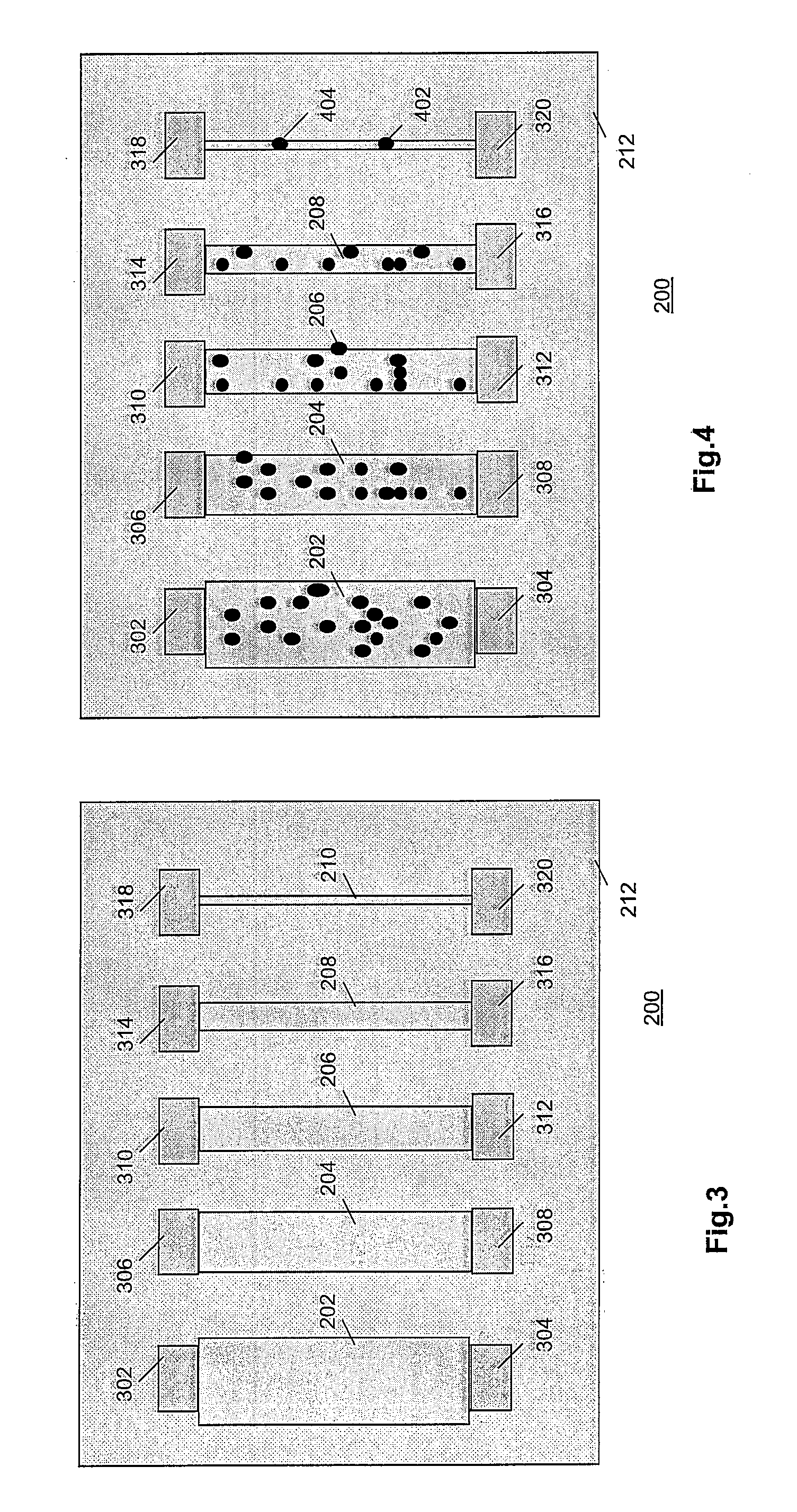
[0029]FIG. 2 is a diagram of an array 200 of differently sized strips 202, 204, 206, 208 and 210 of a material sensitive to corrosion for use in a humidity sensor according to the invention. Strips 202-210 are formed on a substrate 212. Typically, array 200 is manufactured in a semiconductor process, e.g., CMOS, using lithographic exposure and dry-etching, on substrate of a semiconductor material, e.g., silicon. The material that forms strips 202-210 comprises, e.g., a metal that is conventionally deposited in such a process to form interconnects. Preferably, the spaces between strips 202-210 are filled with another material (not shown) that is much less sens...
PUM
 Abstract
Description
Claims
Application Information
 - R&D
- Intellectual Property
- Life Sciences
- Materials
- Tech Scout
- Unparalleled Data Quality
- Higher Quality Content
- 60% Fewer Hallucinations
Browse by: Latest US Patents, China's latest patents, Technical Efficacy Thesaurus, Application Domain, Technology Topic, Popular Technical Reports.
© 2025 PatSnap. All rights reserved.Legal|Privacy policy|Modern Slavery Act Transparency Statement|Sitemap|About US| Contact US: help@patsnap.com


