Thermoelectric conversion module, and heat exchanger, thermoelectric temperature control device and thermoelectric generator employing the same

Inactive Publication Date: 2010-08-05
KK TOSHIBA +1
View PDF15 Cites 38 Cited by
  • Summary
  • Abstract
  • Description
  • Claims
  • Application Information

AI Technical Summary

Benefits of technology

[0008]According to an aspect of the present invention, there are provided a thermoelectric conversion module whose practical use and reliability are improved by improving mechanical prope

Problems solved by technology

In addition, a temperature difference and a heat cycle are often produced between top and bottom surfaces of the thermoelectric conversion module in actual use.
Therefore, the thermoelectric conversion module having many bonded portions of different materials has a problem that it is hard to secure reliability in a high temperature environment of, for example, 300° C. or higher for a long period.
Fracture of the thermoelectric module mo

Method used


Image

  • Thermoelectric conversion module, and heat exchanger, thermoelectric temperature control device and thermoelectric generator employing the same
  • Thermoelectric conversion module, and heat exchanger, thermoelectric temperature control device and thermoelectric generator employing the same
  • Thermoelectric conversion module, and heat exchanger, thermoelectric temperature control device and thermoelectric generator employing the same

Examples


example 1

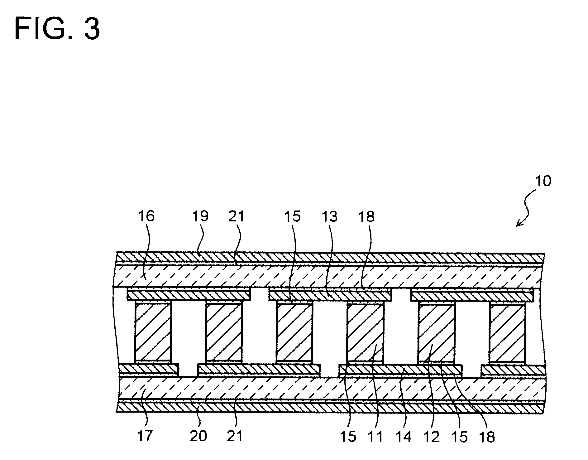
[0055]The thermoelectric conversion module whose structure is shown in FIG. 3 was produced by the following procedure. First, a production example of the thermoelectric element is described.

[0056](N-Type Thermoelectric Element)

[0057]Ti, Zr and Hf each having a purity of 99.9%, Ni and Sn each having a purity of 99.99% and Sb having a purity of 99.999% were prepared as raw materials. They were weighed and mixed so as to have a composition (Ti0.3Zr0.35Hf0.35)NiSn0.994Sb0.006. The material mixture was charged into a copper hearth which was water cooled in an arc furnace, and the furnace interior was evacuated to 2×10⁻³ Pa. Then, Ar having a high purity of 99.999% was introduced to have −0.04 MPa, and the material mixture was arc-melted in the decompressed Ar atmosphere.

[0058]The obtained metal lump was pulverized to produce alloy powder having a particle diameter distribution peak in two ranges of 20-30 μm and 80-90 μm. The alloy powder was filled into a 100-mm carbon mold and undergone...

example 2

[0072]In Example 2, the alloy powder used as the raw material to be sintered for the thermoelectric element was produced by the atomization process. The atomization process is relatively easy to control a particle diameter, and alloy powder having a distribution peak in two ranges of 20-30 μm and 80-90 μm was produced in the same manner as in Example 1. The n-type and p-type thermoelectric elements were produced in the same manner as in Example 1 except that the above alloy powder was used, and a thermoelectric conversion module was also produced similarly. The TCT test was performed on the obtained thermoelectric conversion module under the same conditions as in Example 1. As a result, it was confirmed that even after the operation was repeated for 1000 times or more, no break or shape change was observed in the thermoelectric element, and the initial performance was maintained.

examples 3 and 4

[0073]The hot press of the thermoelectric element preparation conditions (sintering conditions) of Example 1 was changed to HIP, and a thermoelectric element having mechanical properties different from those of Example 1 was produced. Thermoelectric conversion modules were produced in the same manner as in Example 1 except that the above thermoelectric element was used. The thermoelectric conversion modules were undergone the TCT test. Table 3 shows the mechanical properties of the individual thermoelectric elements and the TCT evaluated results of the thermoelectric conversion modules. The TCT evaluated results in Table 3 show the number of times that breakage, peeling and the like did not occur at the thermoelectric element and the bonded portion when it was determined that the high temperature side of each of the individual thermoelectric conversion modules was 500° C. and the low temperature side was 25° C., and an operation of keeping the above condition for 10 minutes and lowe...


PUM

PropertyMeasurementUnit
Temperatureaaaaaaaaaa
Fractionaaaaaaaaaa
Pressureaaaaaaaaaa

Abstract

A thermoelectric conversion module (10) comprises a first electrode member (13) arranged on a low temperature side, a second electrode member (14) arranged on a high temperature side, and p-type and n-type thermoelectric elements (11 and 12) arranged between and connected electrically with both the first and second electrode members (13 and 14). The thermoelectric elements (11 and 12) are composed of a thermoelectric material (half-Heusler material) containing an intermetallic compound having an MgAgAs crystal structure as a main phase and have a fracture toughness value K1C of not less than 1.3 MPa·m1/2 and less than 10 MPa·m1/2.

Description

TECHNICAL FIELD[0001]The present invention relates to a thermoelectric conversion module using a thermoelectric material containing an intermetallic compound having an MgAgAs type crystal structure as a main phase, and a heat exchanger, a thermoelectric temperature control device and a thermoelectric generator employing the same.BACKGROUND ART[0002]The thermoelectric element is expected as a device for recovering the energy which has been discarded as exhaust heat into the atmosphere. The thermoelectric element is used as a thermoelectric conversion module having p-type thermoelectric elements (p-type thermoelectric semiconductors) and n-type thermoelectric elements (n-type thermoelectric semiconductors) which are alternately connected in series. To apply the thermoelectric conversion module to a thermoelectric generator for generating electric power from waste heat or the like, a thermoelectric element usable in a high temperature environment of 300° C. or higher is demanded.[0003]...

Claims


Application Information

Patent Timeline
IPC IPC(8): H01L35/30H01L35/20
CPCC22C12/00C22C13/00H02N1/08H01L35/20H01L35/18H10N10/853H10N10/854
Inventor HIRONO, SHINSUKEOKAMURA, MASAMIKAWASHIMA, FUMIYUKI
Owner KK TOSHIBA
Why Eureka
Try Eureka