Laser scanning projection device

a projection device and laser technology, applied in the field of projection devices, can solve the problems of complicated risk levels for the eye, high laser power may be harmful to the eyes of a person, etc., and achieve the effect of lowering the risk of eye damag

Inactive Publication Date: 2010-08-05
KONINKLIJKE PHILIPS ELECTRONICS NV
View PDF7 Cites 8 Cited by
  • Summary
  • Abstract
  • Description
  • Claims
  • Application Information

AI Technical Summary

Benefits of technology

[0005]It is an object of the present invention to provide a projection device which lowers the risk for damage of the eye when a person gets

Problems solved by technology

Such high levels of laser power may be harmful for the eyes of a person that gets into the scanning cone of the projection system and happens to look directly into the beam.
While the brightness of the projected image

Method used


Image

  • Laser scanning projection device
  • Laser scanning projection device
  • Laser scanning projection device

Examples


Embodiment Construction

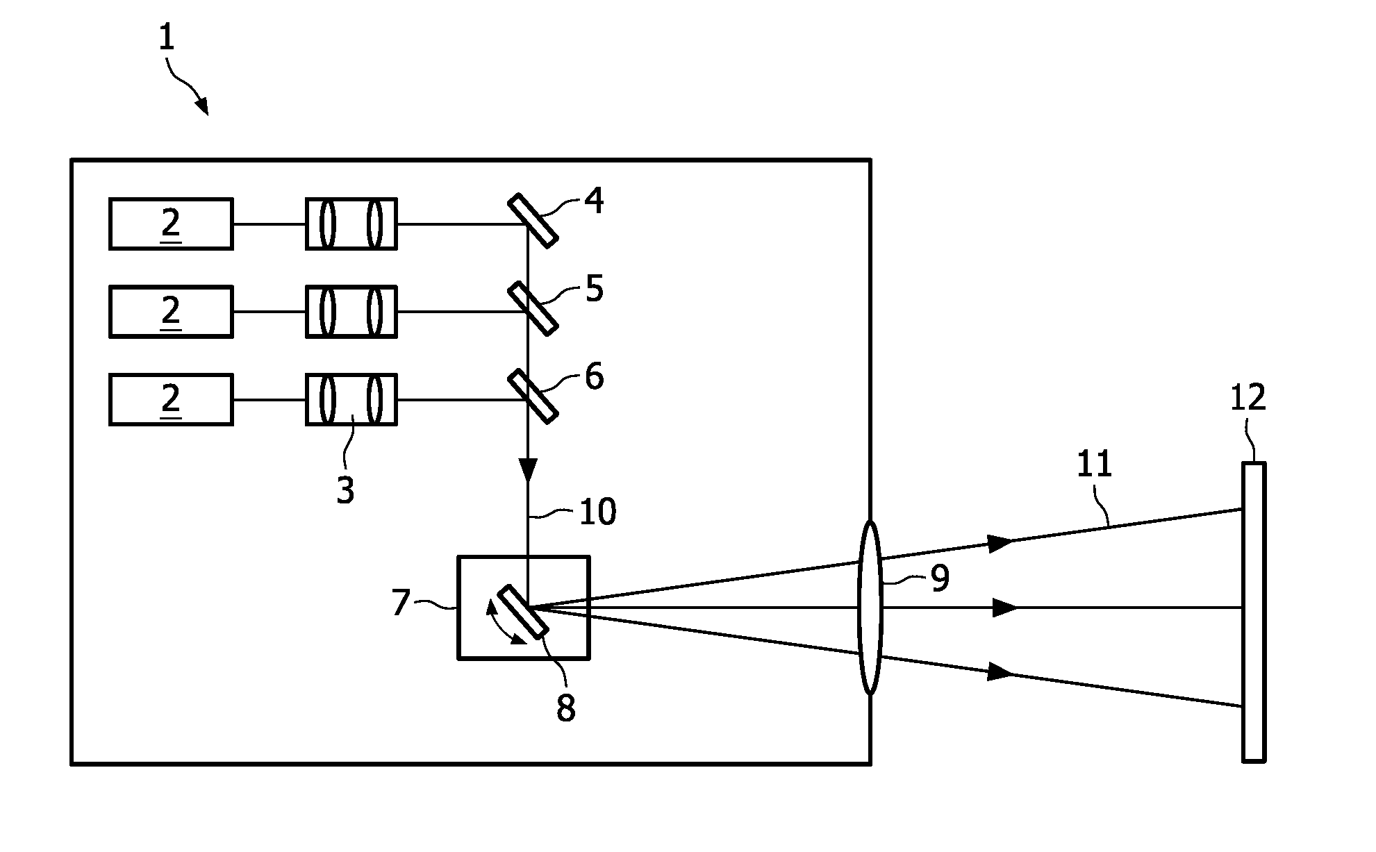
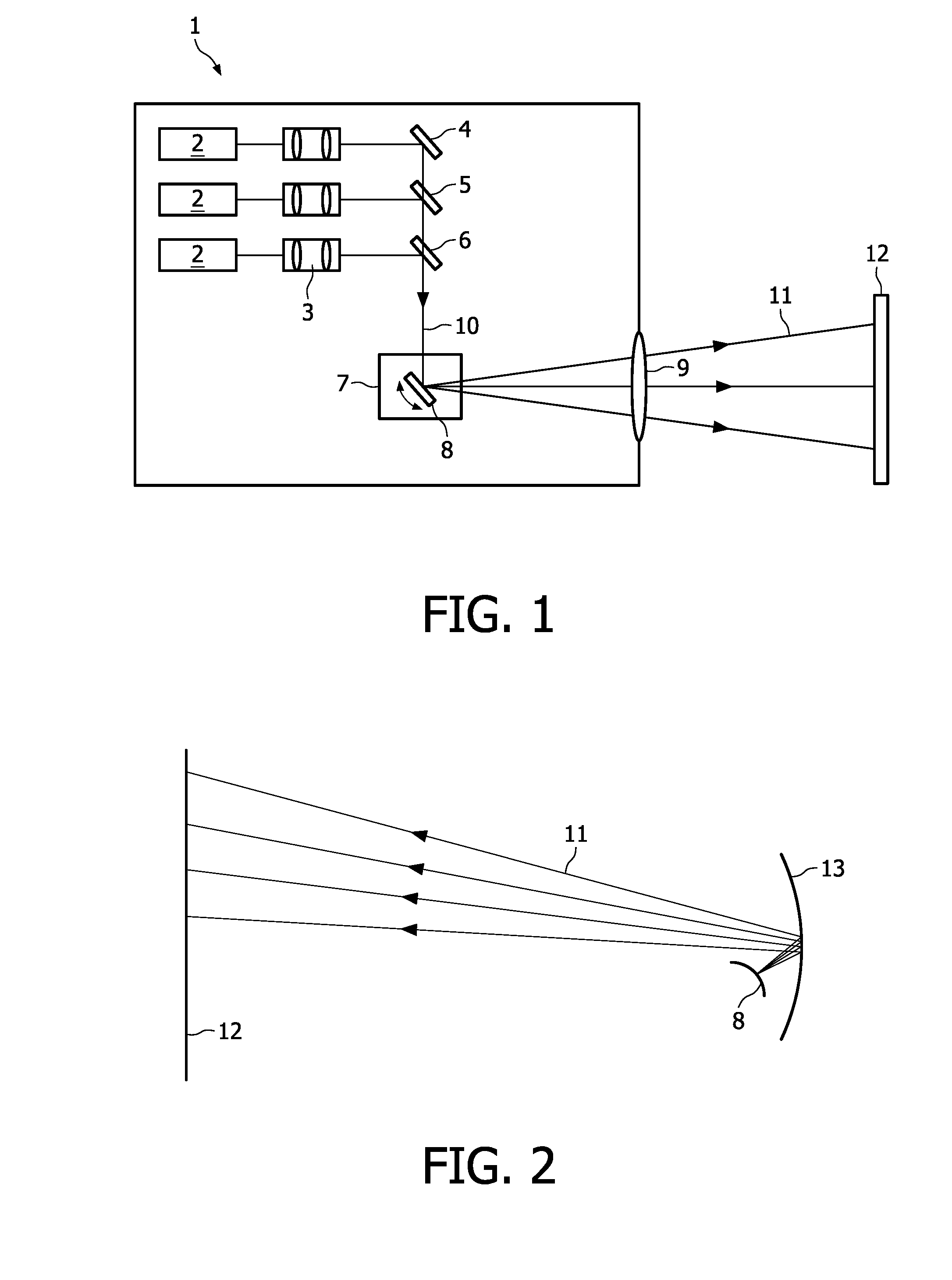
[0024]FIG. 1 is a schematic view of an example of the projection device 1 according the present invention. In this device 1 three laser light sources 2 emitting red (R), green (G) and blue (B) laser light beams are included. The laser light sources 2 may be for example laser diodes. The divergent laser beams emitted by these laser light sources 2 are collimated by a collimating optics 3 and combined to form one single laser beam 10. The combination is made via dielectric mirrors 4, 5, 6. Dielectric mirror 4 is designed to reflect light in the red wavelength region. Dielectric mirror 5 reflects in the green wavelength region and is transparent in the red wavelength region, whereas dielectric mirror 6 reflects in the blue wavelength region and is transparent in the red and green wavelength regions. The combined single laser beam 10 is directed to a 2D scanning unit 7, which contains at least one scanning mirror 8. In FIG. 1 only for illustrative purposes one scanning mirror 8 is depic...


PUM


Abstract

The present invention relates to a projection device comprising at least one laser light source (2) and a scanning unit (7) arranged for scanning a projection area with a laser beam emitted from said laser source (2). The laser beam is adapted to be divergent at least when leaving the scanning unit (7) and a re-focusing optical element (9, 13) for focusing or collimating the divergent laser beam is arranged in beam direction behind said scanning unit (7). With the proposed projection device the risk for eye damage when looking into the projection beam is reduced.

Description

FIELD OF THE INVENTION[0001]The present invention relates to a projection device comprising at least one laser light source and a scanning unit arranged for scanning a projection area with a laser beam emitted from said laser light source. Such laser scanning projection devices are mainly used for image projection but can also be designed for example for optically sensing surface contours or surface patterns.BACKGROUND OF THE INVENTION[0002]Laser scanning projection devices, also called laser projectors, which apply 0D light valves, i.e. a modulator of one pixel at a time, in combination with 2D scanning of the laser beam are often referred to as flying spot systems. In these systems typically three laser sources emitting red (R), green (G) and blue (B) light are combined into a single beam which is then scanned over the area of a projection screen. The laser beams of the three primary (RGB) lasers normally are first collimated and made to converge before they are combined into the ...

Claims


Application Information

Patent Timeline
IPC IPC(8): G03B21/28
CPCH04N9/3129G02B26/105
Inventor RITZ, ARND
Owner KONINKLIJKE PHILIPS ELECTRONICS NV
Why Eureka
Try Eureka