Dielectric ceramic and laminated ceramic capacitor

a technology of laminated ceramic capacitors and dielectric ceramics, which is applied in the direction of fixed capacitors, stacked capacitors, fixed capacitor details, etc., can solve the problems of easy deformation of capacitance temperature characteristics and decrease of dielectric constant, so as to improve the dielectric constant of the entire dielectric ceramic, reduce the effect of low dielectric constant phase, and reduce the number of low dielectric constant phases

Active Publication Date: 2010-08-05
MURATA MFG CO LTD
View PDF7 Cites 4 Cited by
  • Summary
  • Abstract
  • Description
  • Claims
  • Application Information

AI Technical Summary

Benefits of technology

[0011]Therefore, an object of the invention is to provide a dielectric ceramic, and a laminated ceramic capacitor configured with the use of the dielectric ceramic, which can solve the problems described above.
[0017]In the dielectric ceramic according to the present invention, the low dielectric constant phase containing Si is distributed more in the secondary phase grains such a way that the ratio of the Si content in the secondary phase grains to the total content of Si in the dielectric ceramic is 40% or more. Thus, while the size of the low dielectric constant phase is increased, the number of the low dielectric constant phase is reduced. Therefore, the effect of the low dielectric constant phase is reduced, thereby improving the dielectric constant of the entire dielectric ceramic.
[0018]When the Si content in the secondary phase grains is made 30 mol % or more in the dielectric ceramic according to the present invention, the secondary phase grains can be reduced in size without increasing the number of the secondary phase grains. Therefore, the uniformity of the dielectric ceramic is increased, thereby allowing the insulation properties and reliability to be enhanced.
[0019]Accordingly, the laminated ceramic capacitor configured with the use of the dielectric ceramic according to the invention improves the dielectric constant of the dielectric ceramic constituting the dielectric ceramic layers, thereby allowing the laminated ceramic capacitor to be reduced in size.

Problems solved by technology

However, thinner dielectric ceramic layers not only make it more difficult to ensure realizing the required electrical insulation properties, but causes the problem that the electric field strength per dielectric ceramic layer is increased which easily decrease the dielectric constant.
In this case, however, the laminated ceramic capacitor will encounter the problem that its temperature characteristic of capacitance is easily degraded.

Method used


Image

  • Dielectric ceramic and laminated ceramic capacitor
  • Dielectric ceramic and laminated ceramic capacitor
  • Dielectric ceramic and laminated ceramic capacitor

Examples


Embodiment Construction

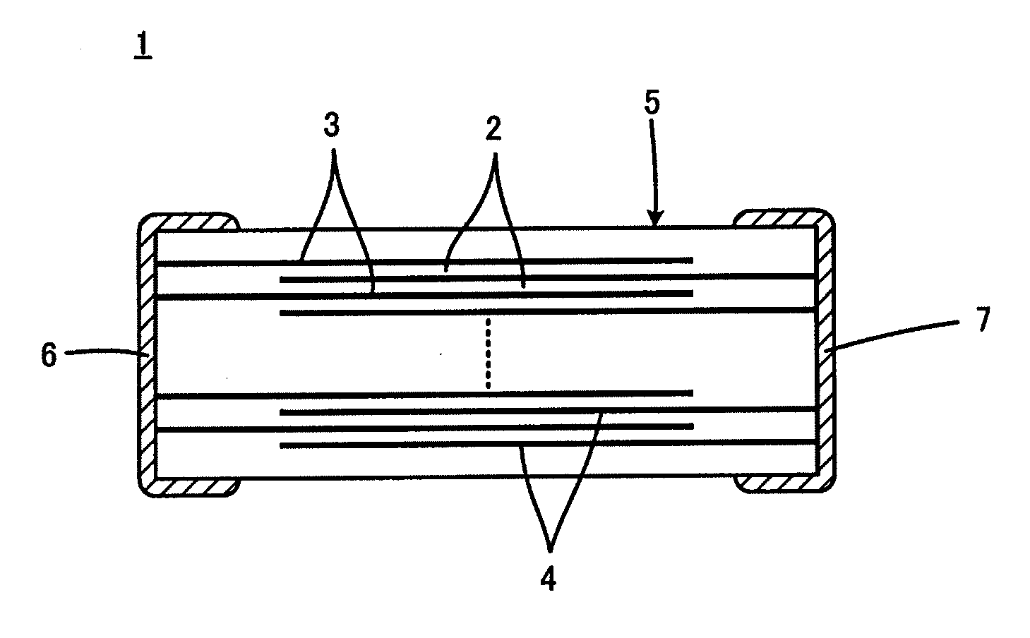
[0023]First, a laminated ceramic capacitor 1 to which a dielectric ceramic according to the invention is applied will be described with reference to FIG. 1.

[0024]The laminated ceramic capacitor 1 includes a capacitor main body 5 composed of a plurality of laminated dielectric ceramic layers 2 and a plurality of internal electrodes 3 and 4 along interfaces between adjacent dielectric ceramic layers 2. The internal electrodes 3 and 4 can contain, for example, Ni, as their main component.

[0025]First and second external electrodes 6 and 7 are formed in positions different from each other on the outer surface of the capacitor main body 5. The external electrodes 6 and 7 can contain Ag or Cu as their main components. In the laminated ceramic capacitor 1 shown in FIG. 1, the first and second external electrodes 6 and 7 are formed on each end faces of the capacitor main body 5 opposed to each other. The internal electrodes 3 and 4 include a plurality of first internal electrodes 3 electrica...


PUM

PropertyMeasurementUnit
dielectric constantaaaaaaaaaa

Abstract

A dielectric ceramic containing ABO3 in which A is Ba, possibly with at least one of Ca and Sr, and B is Ti, possibly with at least one of Zr and Hf as its main component, and Si as a accessory component. The dielectric ceramic includes main phase grains containing the ABO3 main component and secondary phase grains having a composition different from that of the main phase grains. The ratio of the Si content in the secondary phase grains to the total content of Si in the dielectric ceramic is 40% or more so that more Si is distributed in the secondary phase grains. It is preferable that the Si content in secondary phase grains be 30 mol% or more.

Description

BACKGROUND OF THE INVENTION[0001]1. Field of the Invention[0002]The invention relates to a dielectric ceramic, and a laminated ceramic capacitor configured with the use of the dielectric ceramic, and more particularly, relates to an improvement for making the dielectric constant of a dielectric ceramic higher.[0003]2. Description of the Related Art[0004]One of effective means for satisfying the demands of reduction in size and increase in capacitance for laminated ceramic capacitors is making the dielectric ceramic layers included in laminated ceramic capacitors thinner.[0005]However, thinner dielectric ceramic layers not only make it more difficult to ensure realizing the required electrical insulation properties, but causes the problem that the electric field strength per dielectric ceramic layer is increased which easily decrease the dielectric constant. Therefore, there is a demand for increasing the dielectric constant of the dielectric ceramic constituting the dielectric ceram...

Claims


Application Information

Patent Timeline
Patent Type & Authority Applications(United States)
IPC IPC(8): H01G4/12C04B35/46H01G4/005
CPCB82Y30/00H01G4/30C04B2235/3206C04B2235/3224C04B2235/3262C04B2235/3418C04B2235/3436C04B2235/6025C04B2235/652C04B2235/656C04B2235/6565C04B2235/6567C04B2235/6582C04B2235/6584C04B2235/6588C04B2235/781C04B2235/79C04B2235/80H01G4/1227C04B35/4682
Inventor ISHIHARA, MASAYUKI
Owner MURATA MFG CO LTD
Why Eureka
Try Eureka