Apparatus for deploying endoscope

Inactive Publication Date: 2010-08-05
SCOPEGUARD LTD
View PDF3 Cites 34 Cited by
  • Summary
  • Abstract
  • Description
  • Claims
  • Application Information

AI Technical Summary

Benefits of technology

[0022]The protrusion may be defined between two substantially parallel welds between the inner chamber and the outer chamber. The protrusion may be provided with a re-entrant recess (a backwardly facing cut-out) at the proximal end of the sheath by removing an approximately semi-circular portion of the outer chamber. This reduces the height of the protrusion at the proximal end of the sheath, the height gradually increasing with distance from the proximal end of the sheath. Advantageously, the inner and outer sheaths may be temporarily bonded together at the proximal end of the sheath to further reduce friction as the sheath is inserted into the body cavity (so that the protrusion is only formed after the temporary bond breaks). The adhesive may be an adhesive that degrades and becomes less effective on contact with fluid within the body cavity to facilitate insertion of a medical instrument through the channel when the sheath is present in the body cavity.
[

Problems solved by technology

Known sheath arrangements for deploying endoscopes suffer from various problems.
For example, access of the sheath/scope assembly into the body is impeded by small orifices in the body leading to long narrow tubes.
This tends to cause the sheath material to fold or wrinkle at the entrance to the orifice which obstructs insertion of the sheath/scope assembly and is very pain

Method used


Image

  • Apparatus for deploying endoscope
  • Apparatus for deploying endoscope
  • Apparatus for deploying endoscope

Examples


Example

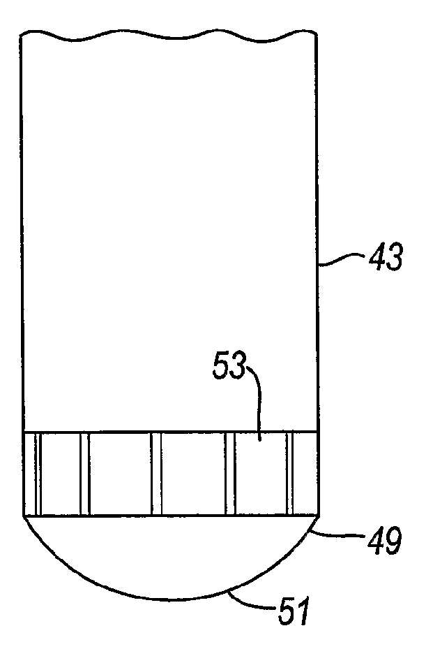
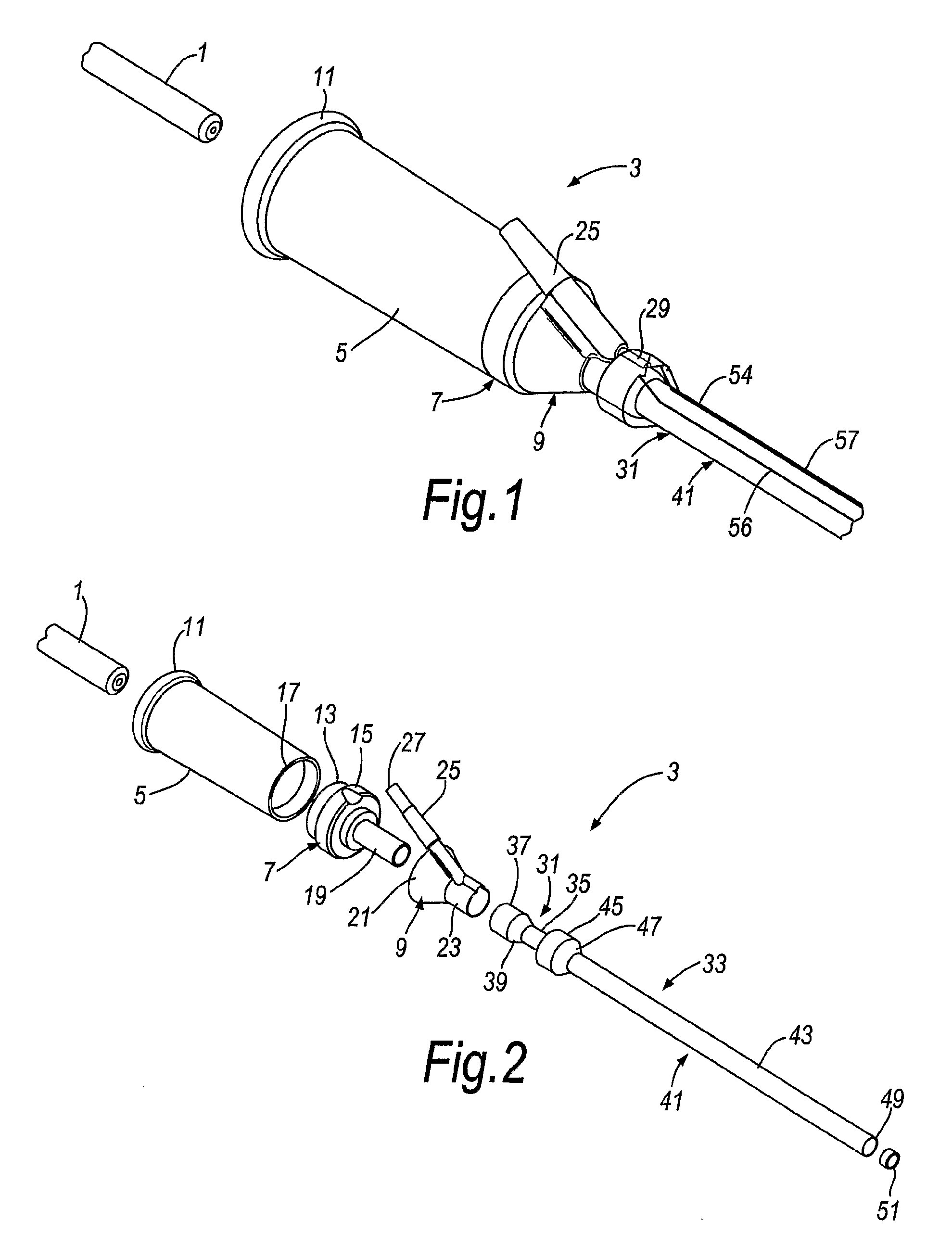
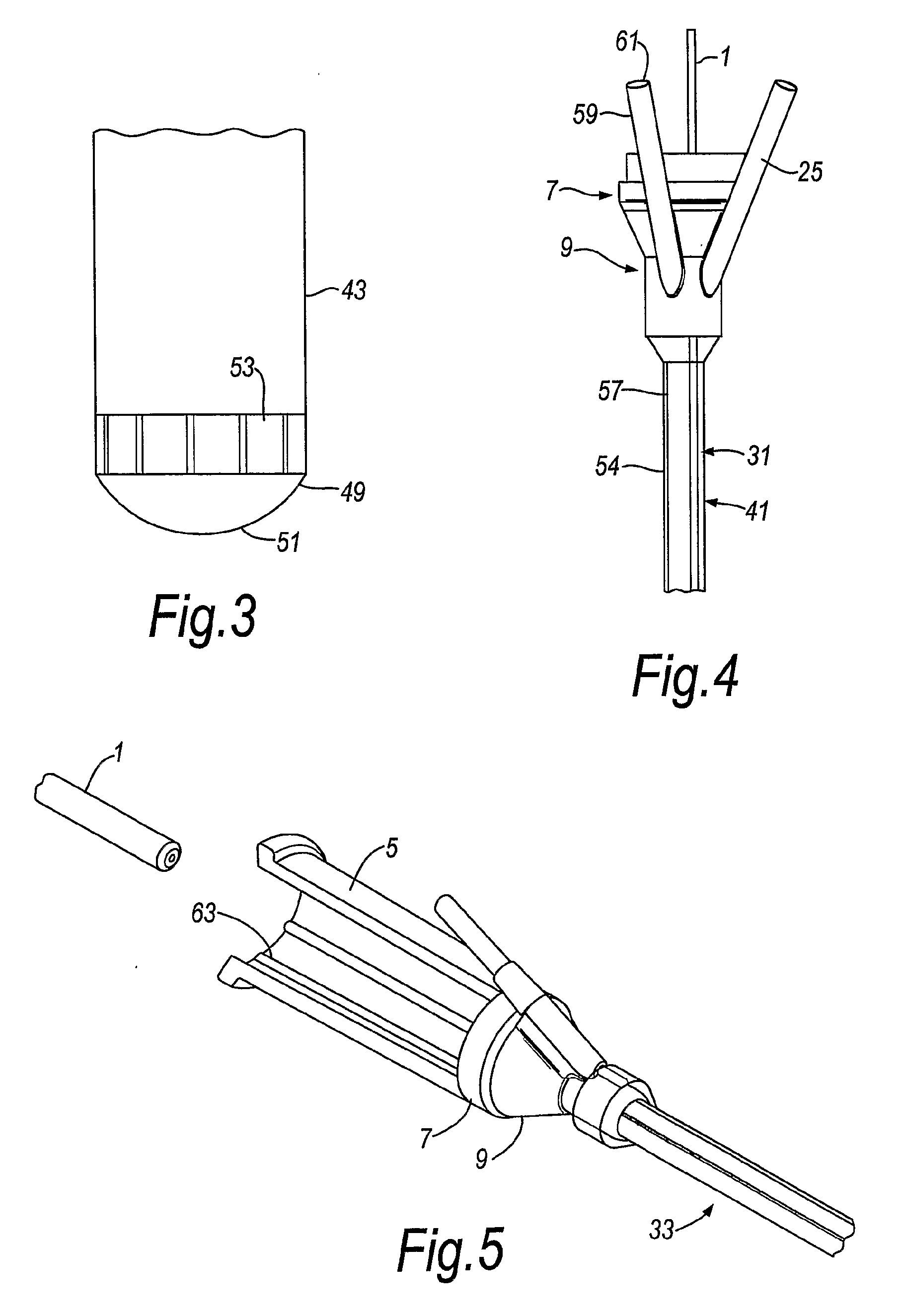
[0055]In the perspective view of FIG. 1 and the exploded perspective view of FIG. 2 the endoscope 1 is shown prior to insertion into the sheath apparatus 3 and a sheath 33. As also shown in FIG. 16,17A and 17B, the sheath apparatus 3 comprises a housing 5 formed of flexible material, an intermediate rigid moulding 7 and a rigid end moulding 9. The flexible housing 5 and rigid mouldings 7 and 9 are advantageously formed by a “twin shot” process which moulds the flexible material of housing 5 to the rigid polymers of mouldings 7 and 9. This allows the housing 5 to accommodate changes in diameter and shape of the endoscope 1.

[0056]The housing 5 comprises a hollow tube of circular cross-section, and may have a collar 11 formed at the endoscope-receiving end thereof. The intermediate moulding 7 includes an annular flange 13 which fits inside the internal diameter of the housing 5 so that the collar 15 of the intermediate moulding 7 abuts against the end face 17 of the housing 5 at the en...


PUM


Abstract

Apparatus for inserting an instrument (1) in a flexible body cavity is disclosed. The apparatus includes a sheath (3) having an inner chamber (31) for accommodating the instrument (1) and an outer chamber (41) surrounding the inner chamber, thereby defining an enclosed space between the inner chamber and the outer chamber Fluid pressure is temporarily applied to thse enclosed space so as to expand the outer chamber to facilitate insertion of the instrument in the body cavity. In another embodiment the inner chamber is expandable to have a diameter equal to or greater than the diameter of the outer chamber, and wherein the outer chamber incorporates one or more lines of weakness for facilitating release and expansion of the inner chamber and withdrawal of the instrument from the inner chamber. In yet another embodiment the sheath includes at its distal end a convex lens for use by a camera in obtaining images of said body cavity. A flexible housing for receiving the instrument may be provided with a relatively rigid intermediate part between the housing and the sheath for guiding the instrument from said housing to said sheath.

Description

TECHNICAL FIELD[0001]The present invention relates to apparatus for inserting an instrument in a body cavity, apparatus for applying an instrument to a body cavity, apparatus for inserting imaging means into a body cavity, and an endoscope end cap.BACKGROUND TO THE INVENTION[0002]An endoscope is a device used to look inside a body cavity, such as a cavity of the human or animal body. When the body cavity is that of a human or animal body, the endoscope is inserted through a natural opening, such as the mouth during a bronchoscopy, the rectum for a sigmoidoscopy or into the bladder to perform a cystoscopy. A cystoscopy is performed with a cystoscope. Generally the scope transmits the image from the inside of the body cavity along its shaft to the operator or a video screen via a fibre optic bundle or a video chip.[0003]For example, a cystoscopy procedure may include initially cleaning the uretheral meatus and applying a local anaesthetic jelly. The cystoscope is then inserted through...

Claims


Application Information

Patent Timeline
IPC IPC(8): A61B1/00
CPCA61B1/00096A61B1/00135A61B1/00142A61B1/12A61B1/01A61B1/307A61B1/31A61B1/00154
Inventor POOLE, GEORGE ANTHONYYOUNG, ANTONY JOHN
Owner SCOPEGUARD LTD
Why Eureka
Try Eureka