Two-dimensional position sensor

a two-dimensional position and sensor technology, applied in the field of sensors, can solve the problems of increasing cost, size and power consumption, significant amount of associated control circuitry, and reliance on passive capacitance measurement techniques, and achieve good response characteristics

Inactive Publication Date: 2010-08-12
ATMEL CORP
View PDF32 Cites 53 Cited by
  • Summary
  • Abstract
  • Description
  • Claims
  • Application Information

AI Technical Summary

Benefits of technology

[0020]These characteristic sizes for the various elements of the sensor have been found to provide good response characteristics, e.g. in terms of linearity of response.
[0021]The sensitive area as a whole may have a characteristic extent on the order of, or less than a dimension selected from the group comprising 30 mm, 25 mm, 20 mm, 15 mm, 10 mm and 5 mm. These are suitable sizes for detecting the position of an object having a characteristic size on the order of the size of a typical user's finger tip. If the sensor is made much greater that 30 mm in size, it can have response flat spots (since it is primarily sensitive to pointing objects adjacent the gaps between the drive and sense electrodes). If the sensor is made too small in size, it can become too insensitive. For example, the sensor may have a characteristic size selected from the group comprising 0.5, 1, 1.5, 2 and 2.5 times the size of a pointing object to be sensed. This helps in allowing a pointing object to modify the capacitive coupling associated with each drive electrode regardless of its position over the sensitive area.
[0022]The sensor may further comprise a mechanical switch and the substrate may be moveably mounted with respect to the mechanical switch so that a movement of the substrate is operable to activate the mechanical switch. This allows a user to control a selection cursor on a display of a device being controlled using the position sensitive aspects of the sensor, and then to make a selection by pressing down on the sensor to activate the mechanical switch, for example. A microcontroller for operating the sensor may be operable to supply a drive signal to a drive electrode through an input / output (I / O) connection at one time, and to sample the status of the mechanical switch through the same input / output (I / O) connection at a another different time. This allows one, or more, mechanical switches to be employed without requiring extra input / output lines for the sensor controller.

Problems solved by technology

To control this many sensors a significant amount of associated control circuitry is required.
This increases cost, size and power consumption.
However, there are some drawbacks associated with its reliance on passive capacitance measurement techniques.
This places some constraints on how the sensors can be integrated into a device.
This means sensors based on passive capacitance measurement techniques will often under-perform if they are located in a device over, or near to, a display screen.
This is because the strong coupling to ground through the screen itself reduces the sensitivity to additional coupling to ground caused by an approaching finger.
Furthermore, the capacitance measurement circuitry associated with passive sensors is generally of high input impedance.
This makes passive sensors prone to electrical noise pick up, e.g. radio frequency (RF) noise.
This can reduce reliability / sensitivity of the sensor and also places further constraints on sensor design (e.g. there is limited freedom to use relatively long connection leads / traces between the sensing electrodes and associated circuitry.

Method used


Image

  • Two-dimensional position sensor
  • Two-dimensional position sensor
  • Two-dimensional position sensor

Examples


Embodiment Construction

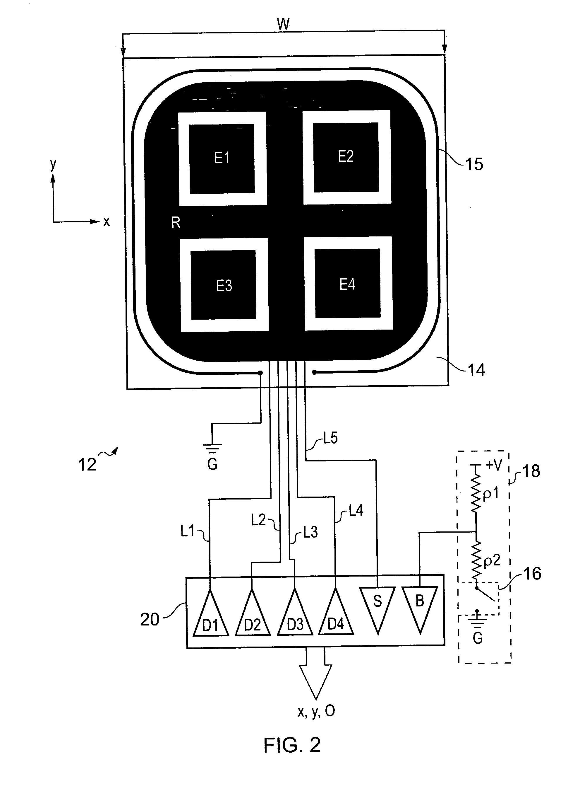
[0037]FIG. 2 schematically shows a sensor 12 for determining a position of an object in two dimensions according to an embodiment of the invention. In this example the two directions are a horizontal direction X and a vertical direction Y for the orientation of the sensor shown in FIG. 2.

[0038]The sensor 12 comprises a substrate 14 bearing an electrode pattern defining a sensitive area of the sensor and a controller 20. The sensor also comprises a mechanical switch 16 (shown highly schematically in FIG. 2) and associated switch circuitry 18 (comprising voltage supply +V; first and second resistors ρ1 and ρ2; connection to a system reference potential (ground) and associated wiring).

[0039]The electrode pattern consists of four drive electrodes E1, E2, E3, E4 arranged in a two-by-two array and a single electrically continuous sense electrode R arranged to extend around the four drive electrodes. The controller 20 provides the functionality of four drive channels D1, D2, D3, D4 for sup...


PUM


Abstract

A sensor for determining a position of an object in two dimensions is provided. The sensor comprises a substrate with a sensitive area defined by a pattern of electrodes arranged thereon. The pattern of electrodes comprises four drive electrodes arranged in a two-by-two array and coupled to respective drive channels, and a sense electrode coupled to a sense channel. The sense electrode is arranged so as to extend around the four drive electrodes (i.e. to wholly or partially surround the drive electrodes, for example, so as to extend adjacent to at least three sides of the drive electrodes). The sensor may further comprise a drive unit for applying drive signals to the respective drive electrodes, and a sense unit for measuring sense signals representing a degree of coupling of the drive signals applied to the respective drive electrodes to the sense electrode. Furthermore the sensor may comprise a processing unit for processing the sense signals to determine a position of an object adjacent the sensor. The functionality of the drive channels, the sense channels, and the processing unit may be provided by a suitably programmed microcontroller.

Description

BACKGROUND OF THE INVENTION[0001]The invention relates to sensors for determining the position of a pointing object, such as a user's finger, in two dimensions.[0002]Capacitive position sensors have recently become increasingly common and accepted in human interfaces and for machine control. For example, in the fields of portable media players it is now quite common to find capacitive touch controls operable through glass or plastic panels. Some mobile (cellular) telephones are also starting to implement these kinds of interfaces.[0003]More recently there has been the appearance of so-called ‘scroll wheels’ as input devices. These are rotary input devices such as those used in the Apple Inc. iPod™ MP3 player. An input device of this type is described in U.S. Pat. No. 7,046,230 [1]. The devices described in U.S. Pat. No. 7,046,230 are based on sensors arranged in zones within a sensing area. Activation of a given sensor indicates that the pointing object is adjacent the corresponding...

Claims


Application Information

Patent Timeline
Patent Type & Authority Applications(United States)
IPC IPC(8): G06F3/041G06F3/033G06F3/0338G06F3/0354
CPCG06F3/016G06F3/0338G06F2203/04105G06F3/044G06F3/03547G06F3/0443H03K17/9622
Inventor YILMAZ, ESATBRUNET, SAMUELHINSON, NIGEL S.D.
Owner ATMEL CORP
Why Eureka
Try Eureka