
Deformable mirror

a mirror and deformation technology, applied in the field of space telescopes, large terrestrial telescopes and adaptive optics, can solve the problems of inability to transport via the present road or rail network, inability to meet the needs of machining of segments at different positions, and difficulty in achieving the effect of reducing the number of mirrors

Inactive Publication Date: 2010-08-12
UNIV LIBRE DE BRUXELIES
View PDF8 Cites 31 Cited by
  • Summary
  • Abstract
  • Description
  • Claims
  • Application Information

AI Technical Summary

Problems solved by technology

However, continuous mirrors with a diameter greater than 8 m constitute a real challenge to produce, especially to polish, and are impossible to transport via the present road or rail network.
These segments need to be polished with a paraboloid shape in order to properly focalize the incoming light into a single point, with the added difficulty that segments at different positions need to be polished to different shapes.
An alternative approach passes by the creation of spherical instead of parabolic reflecting surfaces which would uniformize the shape to be polished in each segment, but this has the consequence of degrading the beam focalization and complicates the optical system subsequent to the primary mirror.
An additional challenge faced by large telescopes is that the disturbances introduced by the atmosphere become increasingly important as the size of the telescope primary mirror increases.
However, this concept presents an inherent high complexity and thus an insufficient reliability, and high manufacturing and maintenance costs.
The development of bimorph mirrors has overcome numerous challenges, including the production of active layers of brittle materials with high aspect ratios, the gluing of these layers to the optical substrates, with the subsequent distortion of the optical surface, the wiring of the independent electrodes to the voltage amplification electronics which was very time consuming, degraded the optical quality and required a significant volume on the back of the mirror.

Method used


Image

  • Deformable mirror
  • Deformable mirror
  • Deformable mirror

Examples


first embodiment

[0044] the coarse curvature is obtained by selecting the materials of the different components (reflective substrate, dielectric layer, horizontal actuators and mass electrode) to have differential thermoelastic distortions. When changing from the temperature of deposition to the temperature of operation, the different layers will undergo differential thermo-elastic distortions resulting in the desired curvature at the temperature of operation.

second embodiment

[0045] the dielectric layer 6 may be a shape memory polymer layer, as illustrated in FIG. 5. Also, a shape memory polymer layer 20 may be applied in contact with the dielectric layer. The shape memory polymer induces the required curvature following a phase change induced by appropriate heating or cooling.

third embodiment

[0046] a metallic coating 21 is applied on the front surface of the reflective substrate, as illustrated in FIG. 6. In this case, the metal layer's surface becomes the reflective surface of the mirror unit. The metal layer can be for example a gold, silver or aluminium layer. In this embodiment, the ‘reflecting substrate’ is formed by the combination substrate / metal layer. The material of the substrate on which the metal layer is deposited may thus be other than a reflecting material. The metal layer introduces a pre-stress on the substrate, resulting in the coarse curvature deformation. Also, the metal may be chosen to obtain a curvature as consequence of differential thermo-elastic distortions (in relation to the deposition temperature) between the metal layer and other components of the unit.


PUM

PropertyMeasurementUnit
Thicknessaaaaaaaaaa
Flexibilityaaaaaaaaaa
Shape memory effectaaaaaaaaaa

Abstract

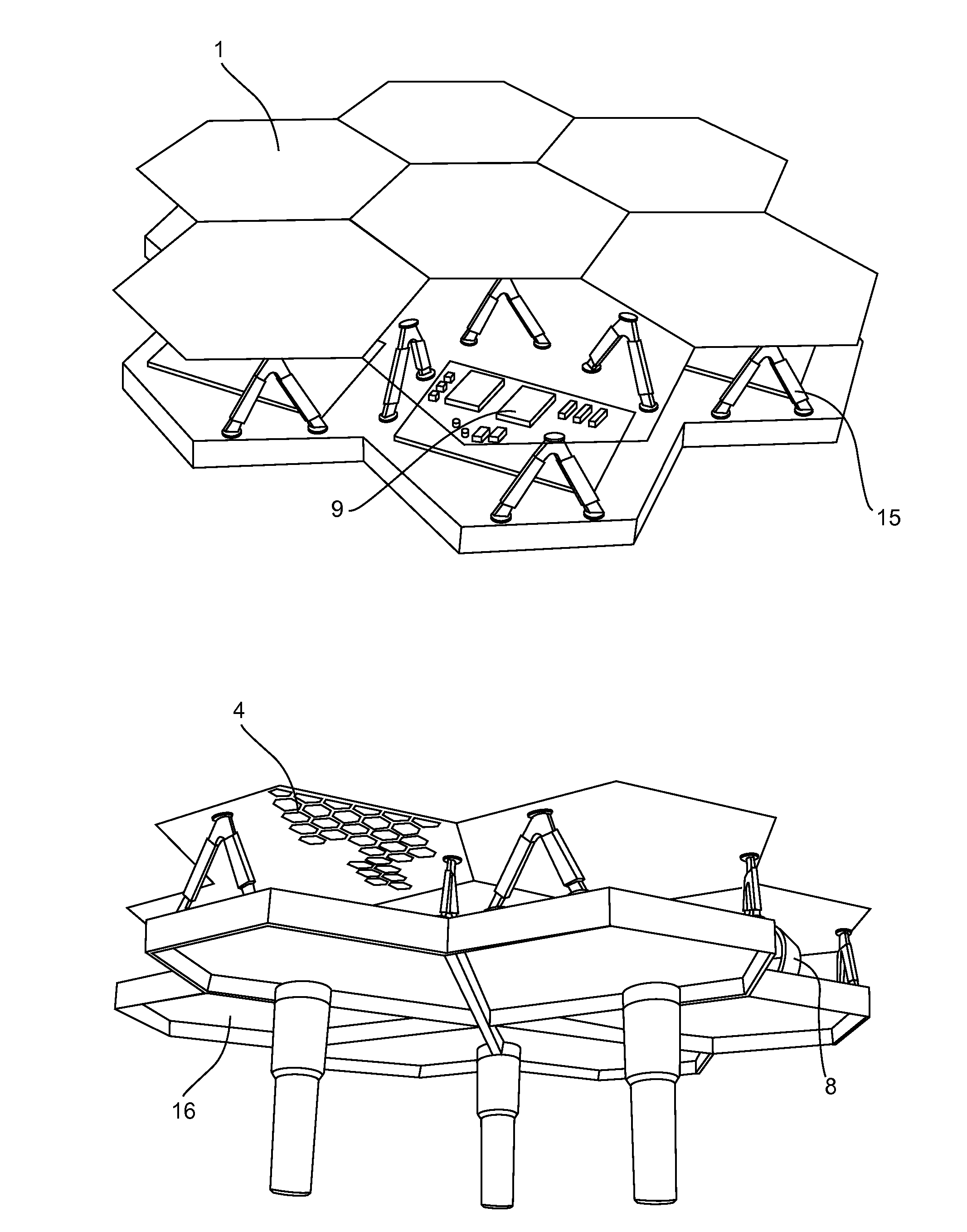
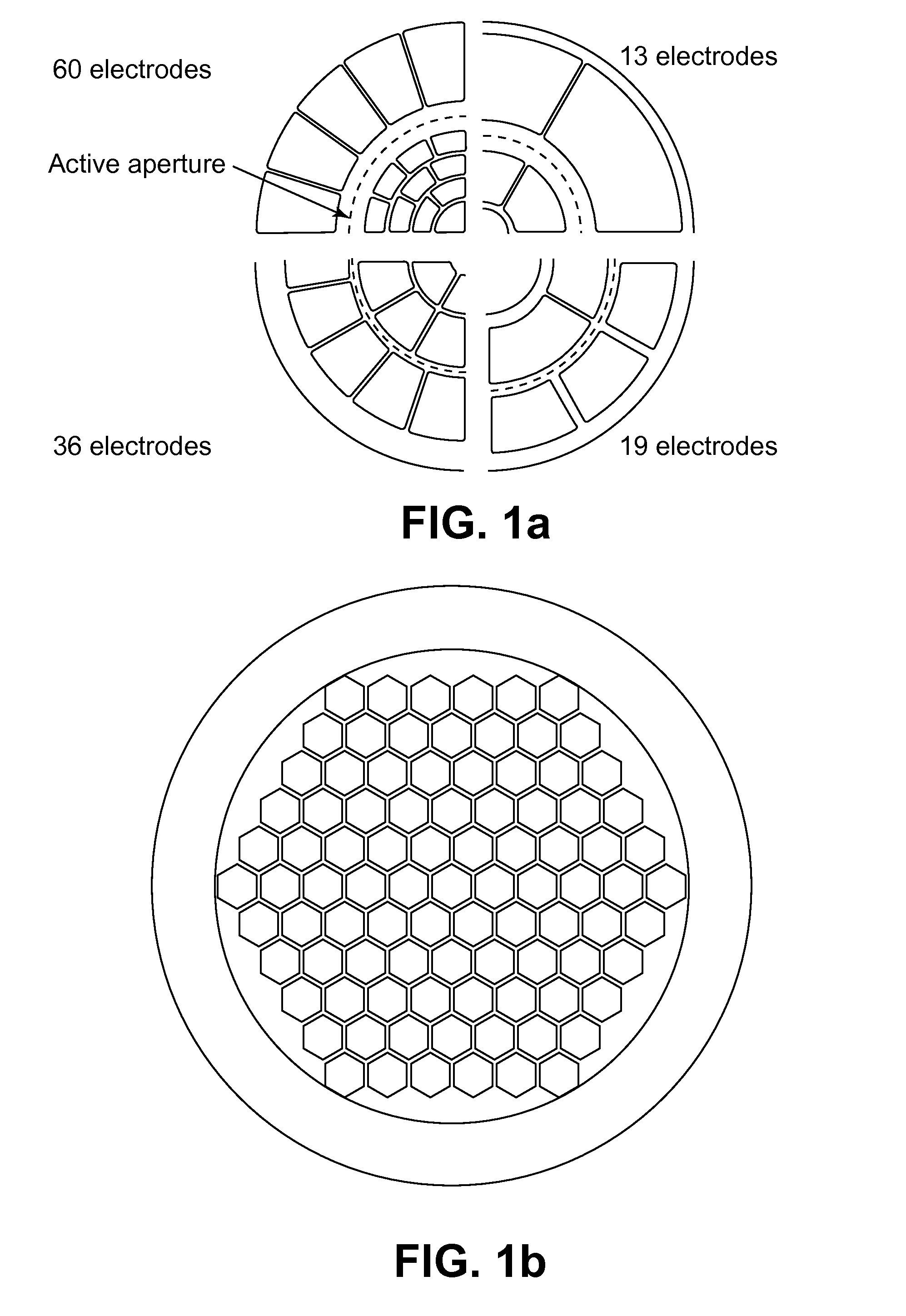
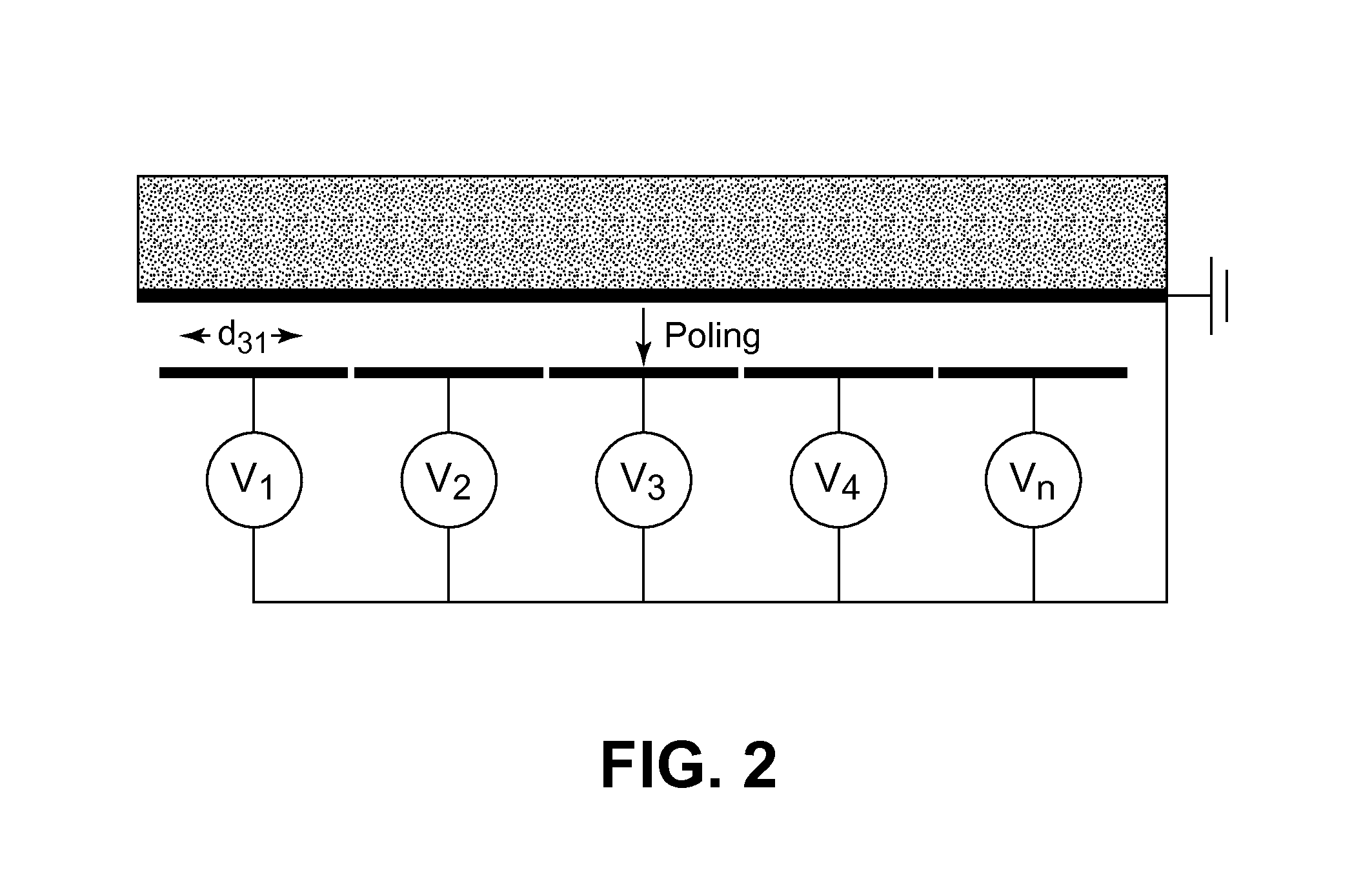
The present invention is related to a deformable mirror comprising individual units (1), each unit including a continuous reflective substrate (2) having a front and back surface, on the back surface of the substrate: a continuous mass electrode (3) and a plurality of in-plane actuators (4) of electrostrictive or piezo-electric material, arranged between the mass electrode (3) and individual addressing electrodes (5).

Description

FIELD OF THE INVENTION[0001]The present invention is related to the field of space telescopes, large terrestrial telescopes and adaptive optics.[0002]The present invention is particularly related to deformable mirrors used in astronomy.[0003]The present invention is also related to a method to fabricate such deformable mirrors.STATE OF THE ART[0004]In astronomy, the larger the size of the primary mirror of a telescope, the finer the details of a scientific target that can be resolved. However, continuous mirrors with a diameter greater than 8 m constitute a real challenge to produce, especially to polish, and are impossible to transport via the present road or rail network. The solution found was to build very large primary mirrors out of independent segments. The Keck and the SALT telescopes, with diameters in the order of 10 m constitute the most successful implementations of this concept. The relative position and orientation between these segments is controlled in three rigid bo...

Claims


Application Information

Patent Timeline
IPC IPC(8): G02B7/185B23P17/04
CPCG02B26/06Y10T29/49826G02B26/0858
Inventor PREUMONT, ANDRERODRIGUES, GONCALO
Owner UNIV LIBRE DE BRUXELIES
Learn More