Apparatus for transmitting data between two systems which move relative to one another

a technology of two systems and transmitting data, applied in the field of transmitting data between two systems, can solve the problem of widened light pulses, and achieve the effect of easy manufacturing and little disruption

Inactive Publication Date: 2010-08-12
SIEMENS HEALTHCARE GMBH
View PDF7 Cites 7 Cited by
  • Summary
  • Abstract
  • Description
  • Claims
  • Application Information

AI Technical Summary

Benefits of technology

[0028]In one embodiment, the coupling structures are configured in the form of notches with oblique surfaces, and an effective alignment of the radiation is possible using the angle of the oblique surfaces of the notches of the coupling structures, onto the lateral module. In one embodiment, serrated notches are used, as the serrated notches are easy to manufacture. Notches with oblique approximately parallel surfaces may deflect non-coupled-out radiation to a lesser degree, and is the non-coupled-out radiation may be available more effectively (e.g., for a subsequent coupling-out).
[0029]In one embodiment, the coupling structures are cone- or pyramid-shaped, and radiation being coupled in from a plane that is spanned by the direction of the radiation being coupled in and the axis of the optical fiber may be deflected out in a targeted manner. During further propagation, the coupled-in radiation has little contact with further coupling structures and consequently is subject to little disruption in the further propagation.

Problems solved by technology

When a standard step index fiber is used as the optical fiber, the standard step index fiber gives rise to the problem that a light pulse is widened in the course of a movement of the light pulse through the optical fiber due to a mode dispersion occurring.
This disadvantage may be counteracted if the optical fiber has a mode dispersion suppressing property, the mode dispersion (e.g., a widening of a light pulse) being reduced by at least 50% by virtue of the mode dispersion suppressing property.

Method used


Image

  • Apparatus for transmitting data between two systems which move relative to one another
  • Apparatus for transmitting data between two systems which move relative to one another
  • Apparatus for transmitting data between two systems which move relative to one another

Examples


Embodiment Construction

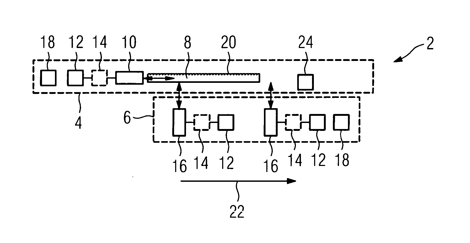
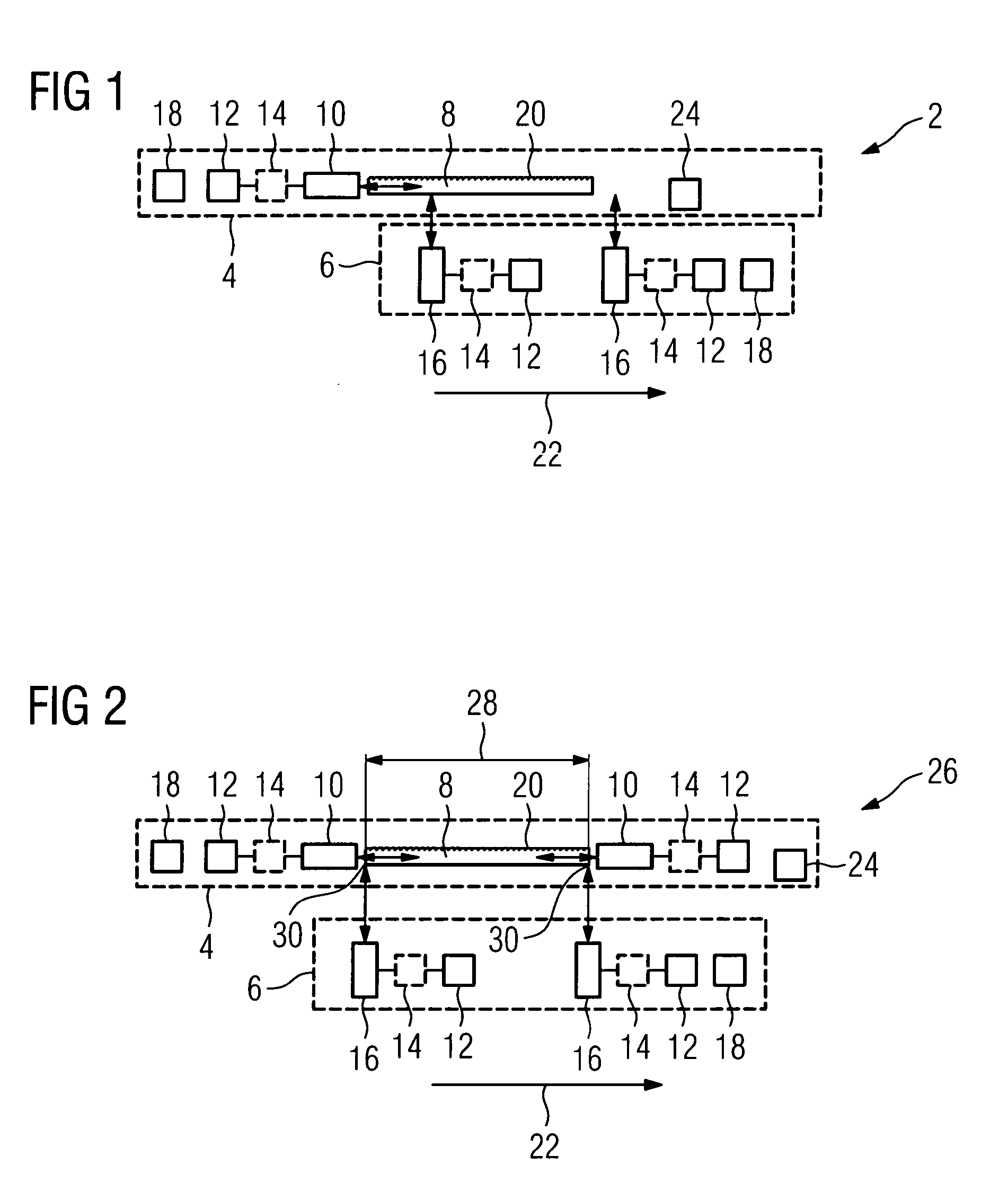
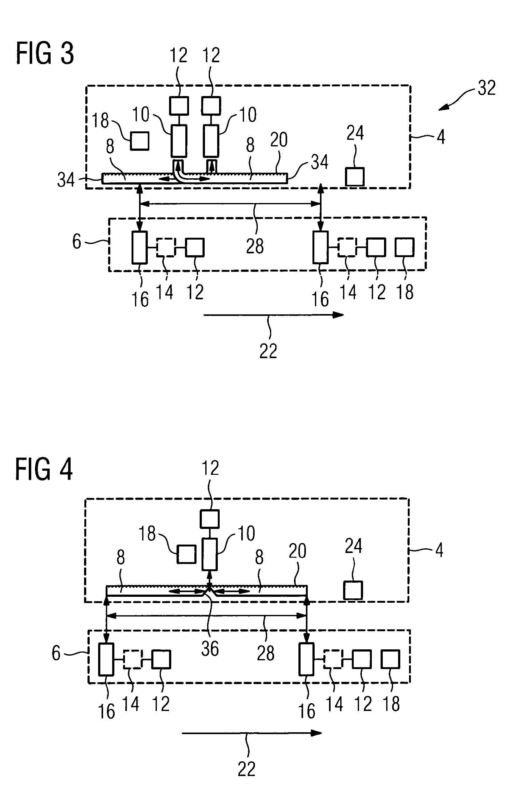
[0054]FIG. 1 shows a schematic representation of one embodiment of an apparatus 2 on a first system 4 (e.g., a stationary system such as an earthbound system having a rail) and a second system 6 (e.g., a moving system such as a rail vehicle that is movable on a rail), moving relative to one another. The stationary system 4 includes an optical fiber 8. In one embodiment, the optical fiber 8 may be a singlemode fiber with a diameter of 10μ which guides light in one mode on account of a structural implementation (e.g., a small diameter). As a result, the fiber exhibits little mode dispersion and is suitable for transmitting data at a data rate of 109 bits / s. In addition, the optical fiber 8 is a polarization-retaining fiber, in which a polarization direction is maintained and, to that extent, a signal is not widened as a result of a widening of both polarization directions due to birefringence.

[0055]Arranged at one end of the optical fiber 8 is an axial module 10, which is provided for...


PUM


Abstract

An apparatus for transmitting data at high data rates, between two systems that move relative to one another is provided. The apparatus includes an optical fiber and an axial module on one of the two systems for the purpose of axial data coupling, using the optical fiber and a lateral module on another of the two systems for the purpose of lateral data coupling using the optical fiber.

Description

[0001]The present patent document is a §371 nationalization of PCT Application Serial Number PCT / EP2008 / 060162, filed on Aug. 1, 2008, designating the United States, which is hereby incorporated by reference. This patent document also claims the benefit of DE 10 2007 041 927.0, filed Sep. 4, 2007, which is also hereby incorporated by reference.BACKGROUND[0002]The present embodiments relate to an apparatus for transmitting data between two systems that move relative to one another.[0003]In a multiplicity of applications, large volumes of data are transmitted between two systems, which move relative to one another. The two systems can be systems rotating relative to one another (e.g., rotary machines of power stations, large motors, radar installations or computed tomography systems) or systems moving translationally relative to one another (e.g., traveling trolleys, rail systems and assembly robots, or a combination of such systems).[0004]Wireless transmission methods using, for exam...

Claims


Application Information

Patent Timeline
Patent Type & Authority Applications(United States)
IPC IPC(8): H04B10/12G02B6/00G02B6/38G02B6/26H04B10/00
CPCG02B6/243G02B6/2817G02B6/2861H04B10/22G02B6/3688G02B6/3692G02B6/4214G02B6/3604H04B10/801
Inventor STARK, MARKUS
Owner SIEMENS HEALTHCARE GMBH
Why Eureka
Try Eureka