
Plasma system and method of producing a functional coating

a technology of plasma system and functional coating, which is applied in the field of plasma system, can solve the problems of high temperature in the plasma jet of several thousand degrees celsius, high cost of method, and complex evacuation techniques, and achieve the effect of higher energy of ions

Inactive Publication Date: 2010-08-12
ROBERT BOSCH GMBH
View PDF12 Cites 3 Cited by
  • Summary
  • Abstract
  • Description
  • Claims
  • Application Information

AI Technical Summary

Benefits of technology

The present invention provides a plasma system with a high-frequency inductively coupled plasma jet source and a method for producing functional coatings on a substrate. The system has advantages over conventional HF-ICP plasma jet sources as it requires a higher energy of the ions to strike the substrate, resulting in a higher mean free path length for the ions. The low vacuum in the chamber where the substrate is located also allows for a higher pressure on the substrate, reducing the thermal load. The method allows for the production of hard carbon coatings, which could previously only be produced by chemical vapor deposition (CVD) methods. The plasma system requires a low vacuum of less than 50 mbar, which can be quickly achieved using conventional pumping devices. The high-rate deposition method is suitable for all substrates and can produce coatings on industrial relevance materials. The electric voltage supplied to the substrate electrode can be varied over time, including its edge steepness, amplitude, and frequency. The variation in voltage can also be correlated with the fluctuation in intensity of the plasma jet. The substrate can be cooled and the plasma jet can be directed at the substrate for more precise deposition.

Problems solved by technology

A conventional method of producing such functional layers is by plasma coating in a medium-high or high vacuum, which requires complex evacuation techniques and yields relatively low coating rates.
Therefore, this method is time-intensive and expensive.
One disadvantage of the known HF-ICP jet sources and plasma systems using such plasma jet sources is the high temperatures in the plasma jet of several thousand degrees Celsius to which the substrate that is to be coated is also exposed.
The choice of usable substrates is considerably restricted in this regard.
Another disadvantage is that to produce layer systems on the substrate, such as those currently produced by CVD methods, for example, a minimum energy of particles impinging on the substrate is often necessary.
This minimum energy of the impinging ions is not achieved with the high-frequency inductively coupled plasma jet sources known in the past and the plasma systems equipped with them.

Method used


Image

  • Plasma system and method of producing a functional coating
  • Plasma system and method of producing a functional coating
  • Plasma system and method of producing a functional coating

Examples


Embodiment Construction

[0029]The present invention is based on a high-frequency, inductively coupled plasma jet source such as that known in a similar form from E. Pfender and C. H. Chang, “Plasma Spray Jets and Plasma Particulate Interaction: Modeling and Experiments,” Convention Volume of the 6th Workshop on Plasma Technology, Technical University of Illmenau. In addition, a coating method similar to that already described in German Published Patent Application No. 199 58 474 is implemented with this system.

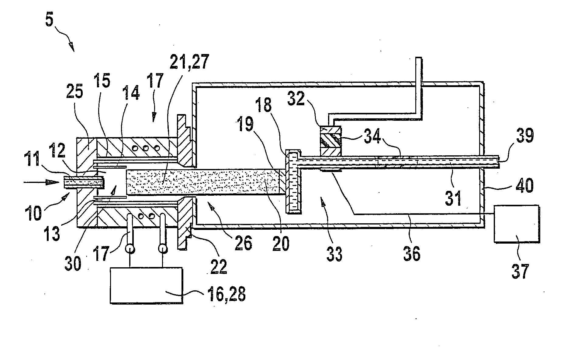
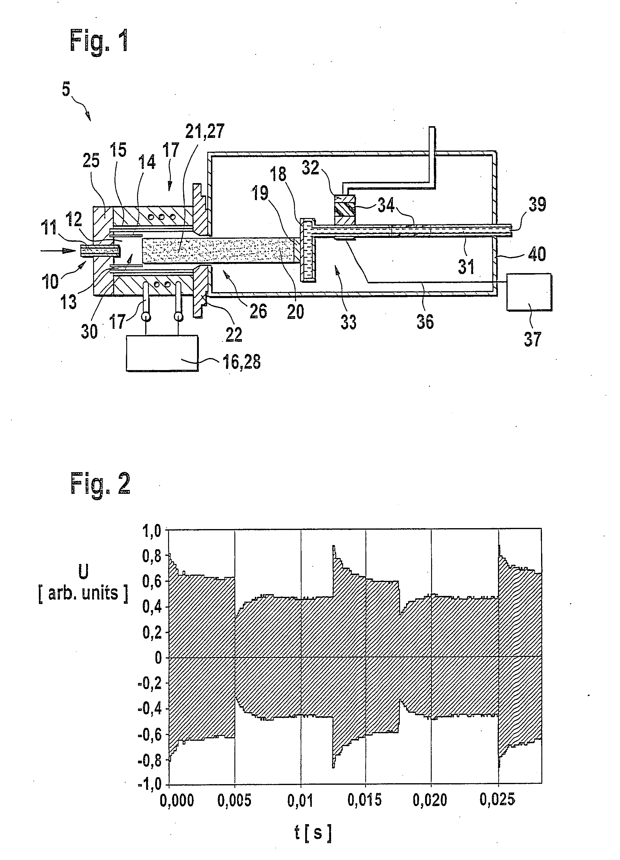
[0030]Specifically, FIG. 1 shows in detail a high-frequency, inductively coupled plasma jet source 5 having a pot-shaped burner body 25, which has on one side an outlet orifice 26, e.g., circular in design and having a diameter of 1 cm to 10 cm, provided with an orifice constrictor 22, which is preferably variably adjustable, i.e., shaped. In addition, plasma jet source 5 has a coil 17 integrated into burner body 25 in the area of outlet orifice 26, e.g., a water-cooled copper coil which may also be ...


PUM

PropertyMeasurementUnit
frequencyaaaaaaaaaa
frequencyaaaaaaaaaa
frequencyaaaaaaaaaa

Abstract

A plasma system has at least one inductively coupled high-frequency plasma jet source having a burner body delimiting a plasma generating space, having an outlet orifice for the plasma jet, and a chamber communicating with the plasma jet source through the outlet orifice, having a substrate situated in the chamber, where it is exposed to the plasma jet. The substrate is situated on a substrate electrode to which an electric voltage may be applied. In addition, a method of producing a functional coating on the substrate using such a plasma system is also described. In a preferred embodiment, during operation of the plasma system, both the plasma jet and the electric voltage on the substrate electrode are pulsed and / or a pressure gradient is maintained between the interior of the plasma jet source and the interior of the chamber.

Description

FIELD OF THE INVENTION[0001]The present invention relates to a plasma system having a high-frequency inductively coupled plasma jet source and to a method of producing a functional coating on a substrate.BACKGROUND INFORMATION[0002]Applying functional coatings to substrates is a widely used method of imparting desired properties to the surfaces of workpieces and / or components. A conventional method of producing such functional layers is by plasma coating in a medium-high or high vacuum, which requires complex evacuation techniques and yields relatively low coating rates. Therefore, this method is time-intensive and expensive.[0003]Thermal plasmas in particular which allow higher coating rates in the range of mm / h to able achieved are suitable for coating substrates in the atmospheric and subatmospheric pressure range. In this regard, reference is made to R. Henne, Contribution to Plasma Physics, 39 (1999) pages 385-397, for example. Of the thermal plasma sources, the high-frequency ...

Claims


Application Information

Patent Timeline
Patent Type & Authority Applications(United States)
IPC IPC(8): C23C4/12H05H1/26B01J19/08H05H1/46C23C16/507C23C16/513C23C16/515H01J37/32H01L21/205H05H1/24H05H1/30
CPCC23C16/513C23C16/515H05H1/30H01J37/32706H01J37/32357
Inventor GROSSE, STEFANHENKE, SASHASPINDLER, SUSANNE
Owner ROBERT BOSCH GMBH
Learn More