Laminated optical film, liquid crystal panel, and liquid crystal display apparatus
a technology of liquid crystal display apparatus and laminated film, which is applied in the direction of optics, instruments, optical elements, etc., can solve the problems of increasing the thickness the image cannot be visually identified in some cases, and the thinning of the liquid crystal display apparatus, etc., to achieve the effect of simplifying the manufacturing steps
- Summary
- Abstract
- Description
- Claims
- Application Information
AI Technical Summary
Benefits of technology
Problems solved by technology
Method used
Image
Examples
example 1
(Production of Retardation Layer)
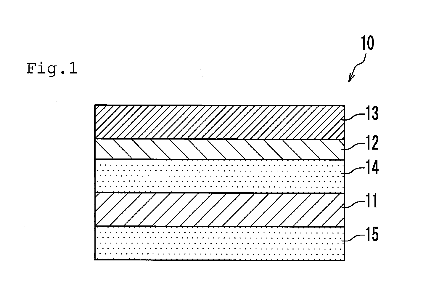
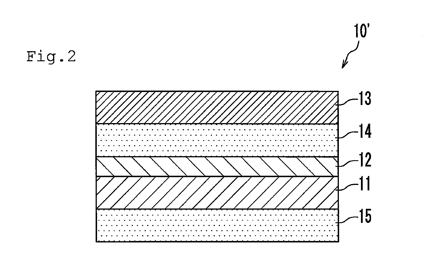
[0111]A polyvinyl alcohol film (having a thickness of 0.1 μm) was formed on the surface of a substrate (TAC film having a thickness of 40 μm). After that, the surface of the polyvinyl alcohol film was subjected to a rubbing treatment with a rubbing cloth in the direction at 45° with respect to the lengthwise direction of the substrate. Thus, an aligned substrate was produced.
[0112]Next, 10 g of a polymerizable liquid crystal showing a nematic liquid crystal phase (available from BASF under the trade name of Paliocolor LC242) and 0.5 g of a photopolymerization initiator for the polymerizable liquid crystal (available from Ciba Specialty Chemicals Inc. under the trade name of IRGACURE 907 and containing 1% of a benzotriazole-based UV absorbing agent) were dissolved in 40 g of toluene. Thus, an application liquid was prepared. Then, the application liquid was applied to the surface of the aligned substrate obtained in the foregoing with a bar coater. Af...
example 2
(Production of Polarizer)
[0120]A polyvinyl alcohol film having a thickness of 80 μm (with an average polymerization degree of 2400 and a saponification degree of 99.9%) was swollen by being immersed in pure water at 30° C. Next, the film was dyed and stretched by a factor of 2.5 while being immersed in a dyeing bath blended with iodine and potassium iodide at 30° C. for 60 seconds. Next, the resultant was stretched by a factor of 2.3 while being immersed in an aqueous solution of boric acid at 40° C. for 60 seconds. Further, the resultant was immersed in an aqueous solution having a potassium iodide concentration of 5% at 30° C. for 5 seconds. After that, the resultant was dried at 50° C. for 4 minutes. As a result, a polarizer (having a thickness of 26 μm) was obtained.
[0121](Production of Laminated Optical Film)
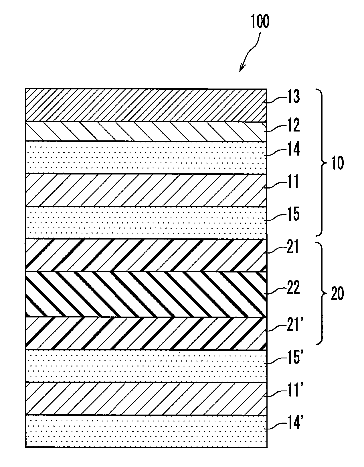
[0122]The retardation layer obtained in Example 1 was laminated on the TAC film side of the TAC film on which the hard coat layer obtained in Example 1 was formed through a...
reference example 1
(Production of Laminated Optical Film)
[0129]A laminated optical film was obtained in the same manner as in Example 1 except that the retardation layer was not laminated.
[0130]The laminated optical films of Examples 1 and 2 of the present invention were much thinner than the laminated optical film of Comparative Example 1. As a result, the laminated optical film of the present invention can contribute to thinning of each of a liquid crystal panel and a liquid crystal display apparatus.
[0131]Transmittance measurement was performed for the retardation layer used in Example 1 of the present invention and the retardation film used in Comparative Example 1 with an UV and visible spectrophotometer (available from JASCO Corporation under the product name of V-570). FIG. 5 illustrates the results. As is apparent from FIG. 5, the transmittance of the retardation layer of Example 1 significantly reduces at a wavelength boundary of around 400 nm as compared to the retardation film of Comparativ...
PUM
 Abstract
Description
Claims
Application Information
 - R&D
- Intellectual Property
- Life Sciences
- Materials
- Tech Scout
- Unparalleled Data Quality
- Higher Quality Content
- 60% Fewer Hallucinations
Browse by: Latest US Patents, China's latest patents, Technical Efficacy Thesaurus, Application Domain, Technology Topic, Popular Technical Reports.
© 2025 PatSnap. All rights reserved.Legal|Privacy policy|Modern Slavery Act Transparency Statement|Sitemap|About US| Contact US: help@patsnap.com


