
Device and a method for determining a component signal with high accuracy

a component signal and high-accuracy technology, applied in the field of audio reproduction methods, can solve the problems of series of characteristic errors, increase of error of most delay interpolation algorithms, and high processing cost of wfs audio reproduction method, so as to improve the utilization of delay interpolation and suppress audible artefacts.

Active Publication Date: 2010-08-19
FRAUNHOFER GESELLSCHAFT ZUR FOERDERUNG DER ANGEWANDTEN FORSCHUNG EV
View PDF7 Cites 43 Cited by
  • Summary
  • Abstract
  • Description
  • Claims
  • Application Information

AI Technical Summary

Benefits of technology

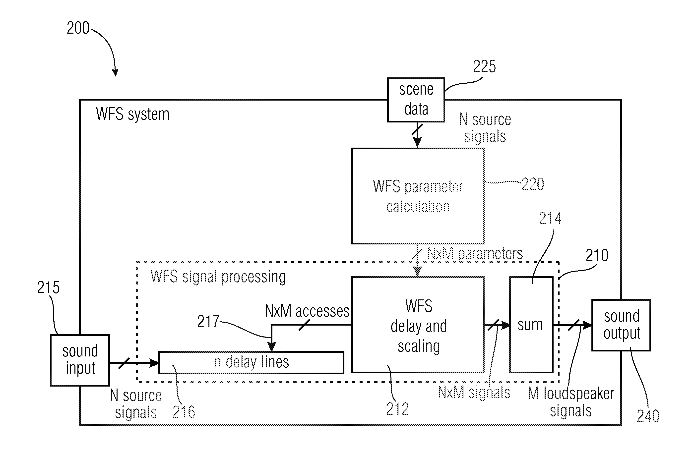
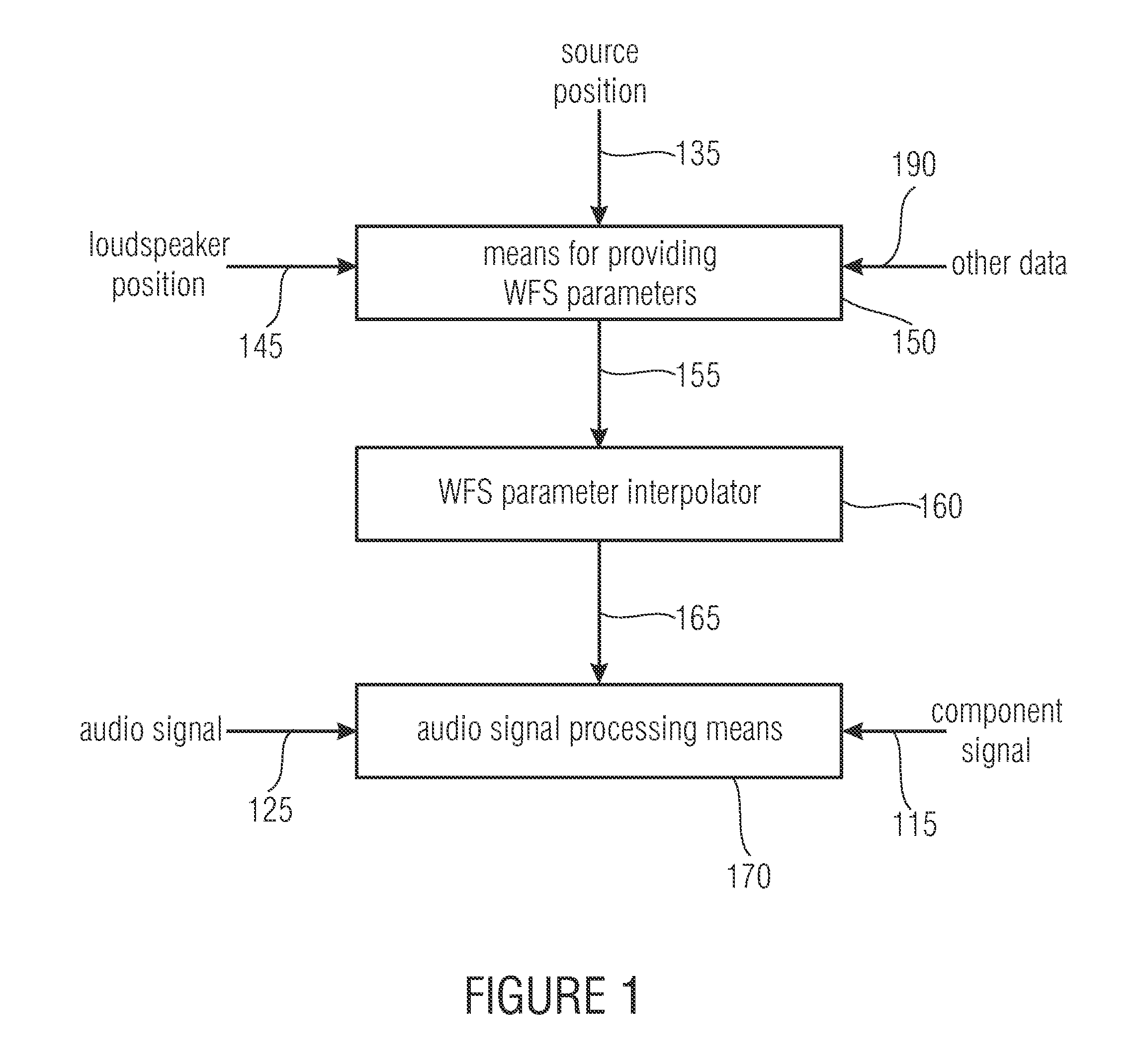
[0071]The idea of the solution to the problem is therefore based on the fact that the complexity of the overall algorithm is reduced by exploiting redundancy. In this context, the delay interpolation algorithm is partitioned such that it is subdivided into a) a portion for calculating intermediate values, and b) an efficient algorithm for calculating the final results.
[0074]In this method, the input signals are converted, by means of oversampling, to a higher sampling rate prior to storing the input signals into a delay line. This is efficiently performed, e.g., by polyphase methods. The number of “upsampled” values which is correspondingly higher is stored in the delay line.
[0080]In a further embodiment, the audio signal processing means is configured to perform oversampling of the audio signal such that said oversampling is performed up to an oversampling rate which ensures a desired level of accuracy. This has the advantage that the second interpolation step becomes redundant as a result.
[0081]Embodiments of the present invention describe WFS delay interpolation which is advantageous, in particular, for audio technology and sound technology within the context of wave field synthesis, since clearly improved suppression of audible artefacts is achieved. The improvement is achieved, in particular, by improved delay interpolation in the utilization of fractional delays and asynchronous sampling rate conversion.

Problems solved by technology

However, rendering moving sources causes a series of characteristic errors that do not occur in the case of static sources.
As has been said, WFS is a method of audio reproduction that is very costly in terms of processing resources.
An important issue is about which quality improvement is to be achieved by the algorithms to be developed.
In addition, many physical laws that are also used in WFS only apply to speeds below the speed of sound.
On the one hand, the error of most delay interpolation algorithms increases sharply as the distance of the frequency range of interest from the Nyquist frequency decreases.
However, since the filter operation is performed only once per input and / or output signal, respectively, the performance requirement is generally moderate.
In addition to the known rendering errors (artefacts) of WFS, a series of further characteristic errors occur with moving sources.
In the event of movements of the virtual source, this pattern changes dynamically and thus produces time-dependent frequency distortion for an observer who is not moving.
This creates a systematic error of the Doppler shift which, however, is relatively small for moderate speeds and is very likely not to be perceived as disturbing in most WFS applications.
The algorithms used for this purpose differ strongly in terms of quality and often produce artefacts that are perceived as disturbing.
Nevertheless, it is undesired in many applications.
FIR filters generally may use a larger number of filter coefficients and, thus, of arithmetic operations, and also, they produce amplitude errors for random fractional delays.
However, it is not possible to influence the phase of an IIR filter as precisely as in the case of an FIR filter.
Most design methods for IIR-FD filters are iterative, and accordingly, they are not suited for real-time applications with variable delays.
This is unfavorable for implementation in a WFS reproduction system, since a multitude of previous output signals would have to be administered.
In addition, utilization of internal states reduces the suitability of IIR filters for variable delays, since the internal state was possibly calculated for a different fractional delay than the current one.
This leads to interferences in the output signal which are referred to as transients.
In addition, however, they exhibit several problems that are to be solved additionally, e.g. the usefulness of suppressing imaging and aliasing artefacts.
However, adhering to the ideal working range results in a minimum value of the delay, which may not be fallen below in order to keep to the causality.
Therefore, methods for delay interpolation, specifically high-quality FD algorithms with long filter lengths, also entail an increase in the system latency.
However, this is generally low as compared to other latencies of a typical WFS rendering system that are determined by the system.
While rounding off the delay to the nearest multiple of the sampling period provides sufficiently good results with static WFS sources, this method results in marked interferences with moving sources.
In connection with the complexity—useful for high rendering quality—of the delay interpolation, high-quality real-time implementation is not practicable.
However, only simple (standard) delay interpolation methods are utilized for realizing the algorithms.
Nevertheless, this operation takes up the major portion of the computational load that may be used within the renderer.BufferwiseDelayLinear.
This method is clearly more costly than the previous ones, and additionally, it exists only in a C++ reference implementation.
Therefore, it is not suitable for being used with real, complex WFS scenes.SamplewiseDelayCubic.

Method used


Image

  • Device and a method for determining a component signal with high accuracy
  • Device and a method for determining a component signal with high accuracy
  • Device and a method for determining a component signal with high accuracy

Examples


Embodiment Construction

[0095]With regard to the description which follows, it should be noted that in the different embodiments, functional elements that are identical or have identical actions bear identical reference numerals and that, therefore, the descriptions of said functional elements are interchangeable in the various embodiments presented below.

[0096]Before the present invention is addressed in detail, the fundamental architecture of a wave field synthesis system shall be presented below with reference to FIG. 11. The wave field synthesis system has a loudspeaker array 700 that is placed in relation to a demonstration area 702. Specifically, the loudspeaker array shown in FIG. 11, which is a 360° array, comprises four array sides 700a, 700b, 700c and 700d. If the demonstration area 702 is a movie theatre, for example, it shall be assumed, with regard to the conventions of front / back or right / left, that the movie screen is located on the same side of the demonstration area 702 on which the sub-ar...


PUM


Abstract

A device for determining a component signal for a WFS system includes a provider for providing WFS parameters, a WFS parameter interpolator, and an audio signal processor. The provider provides WFS parameters for a component signal while using a source position and while using the loudspeaker position at a parameter sampling frequency smaller than the audio sampling frequency. The WFS parameter interpolator interpolates the WFS parameters so as to produce interpolated WFS parameters which are present at a parameter interpolation frequency that is higher than the parameter sampling frequency, the interpolated WFS parameters having interpolated fractions which have a higher level of accuracy than is specified by the audio sampling frequency. The audio signal processor is configured to apply the interpolated fractional values to the audio signal such that the component signal is obtained in a state of having been processed at the higher level of accuracy.

Description

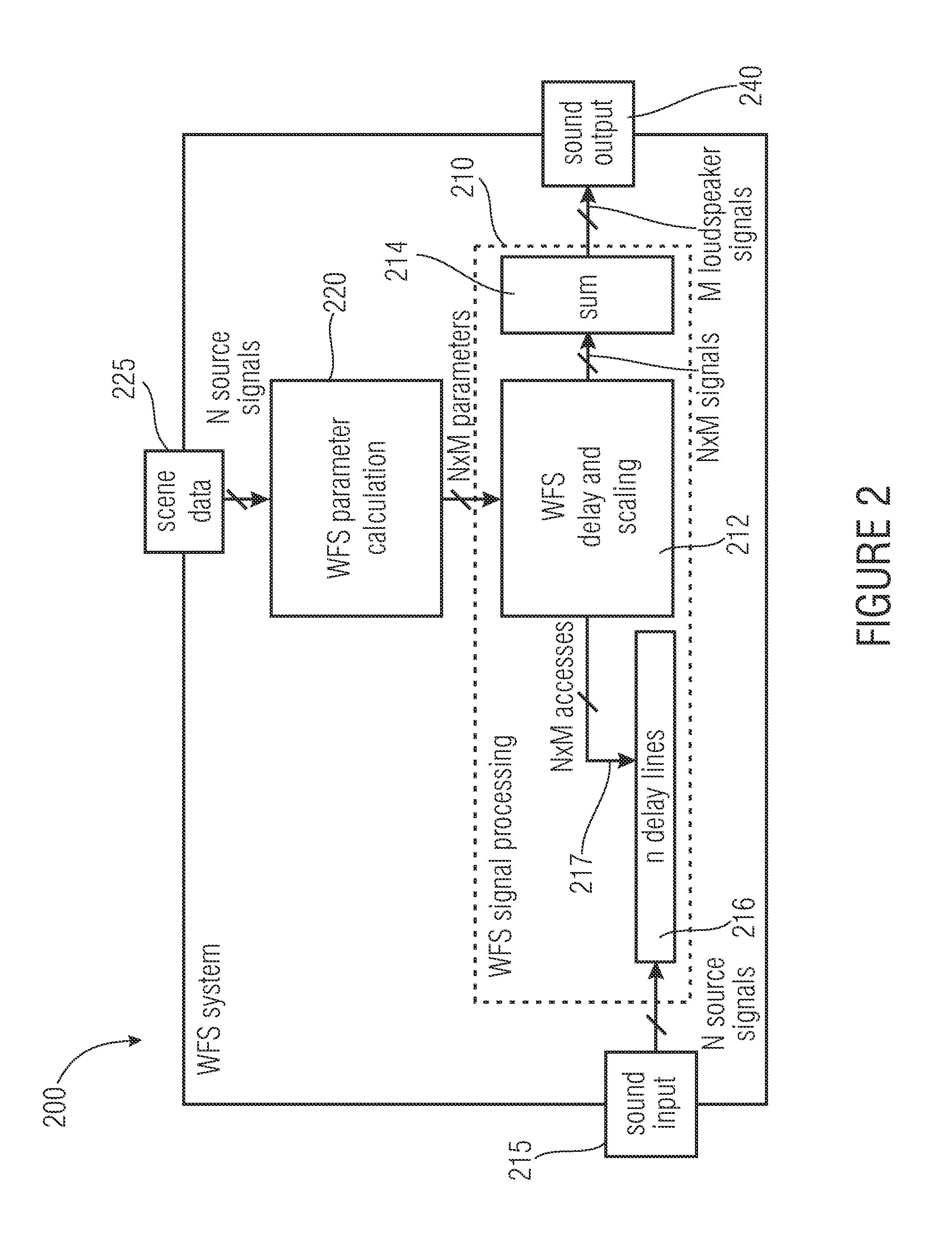
[0001]The present invention relates to a device and a method for determining a component signal with high accuracy for a WFS (wave field synthesis) system and, in particular, to an efficient algorithm for delay interpolation for wave field synthesis rendering, or replay, systems.BACKGROUND OF THE INVENTION[0002]Wave field synthesis is an audio reproduction method for spatial rendering of complex audio scenes that was developed at the Delft University of Technology. Unlike most existing methods of audio reproduction, spatially correct rendering is not restricted to a small area, but extends across an extensive rendering area. WFS is based on a sound mathematical-physical foundation, namely the principle of Huygens and the Kirchhoff-Helmholtz integral.[0003]Typically, a WFS reproduction system consists of a large number of loudspeakers (so-called secondary sources). The loudspeaker signals are formed from delayed and scaled input signals. Since many audio objects (primary sources) are...

Claims


Application Information

Patent Timeline
Patent Type & Authority Applications(United States)
IPC IPC(8): H04R29/00
CPCH04S3/008H04R5/04H04S2420/13
Inventor FRANCK, ANDREASBRIX, SANDRASPORER, THOMAS
Owner FRAUNHOFER GESELLSCHAFT ZUR FOERDERUNG DER ANGEWANDTEN FORSCHUNG EV
Learn More