

Copper Foil for Printed Circuit and Copper-Clad Laminate
a technology of printed circuit and copper-clad laminate, which is applied in the direction of superimposed coating process, coating, capacitors, etc., can solve the problems of decreasing the adhesion strength between copper foil and resin base material, and achieve the effect of high integration of semiconductor devices and effective prevention of penetration into circuit edge parts
Active Publication Date: 2010-08-26
JX NIPPON MINING& METALS CORP
View PDF19 Cites 33 Cited by
- Summary
- Abstract
- Description
- Claims
- Application Information
AI Technical Summary
Benefits of technology
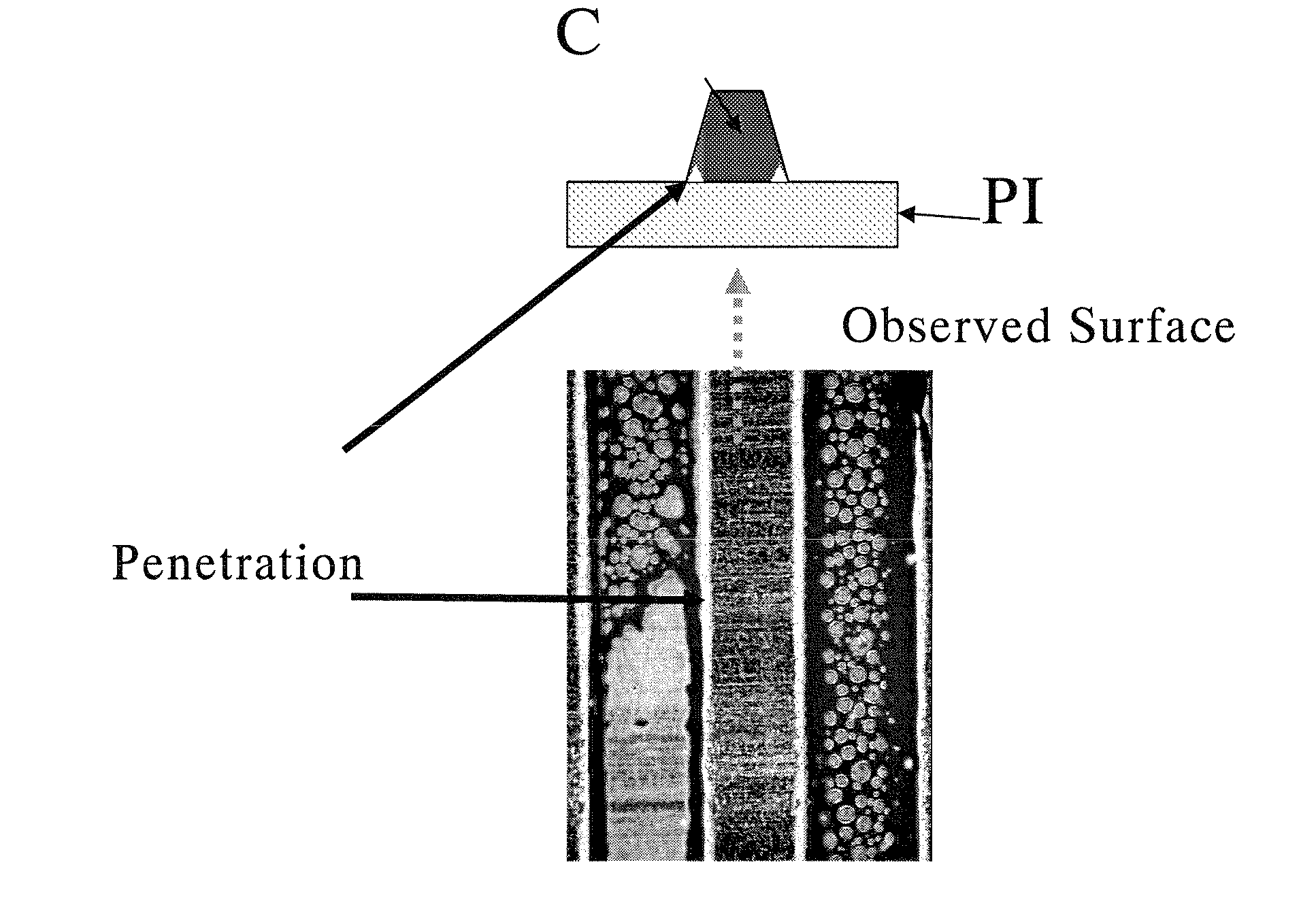
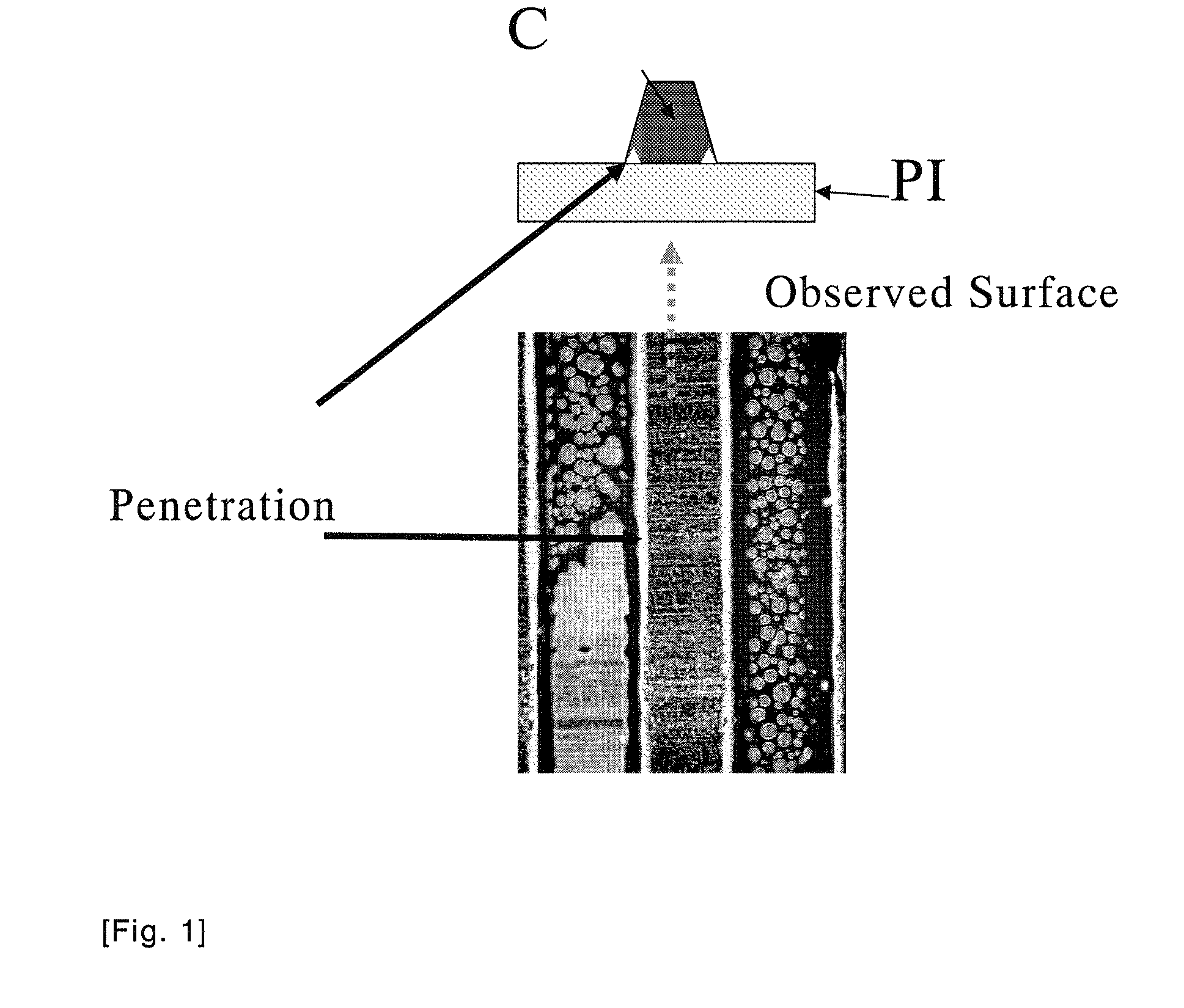
[0021]With the development of electronic equipment, the miniaturization and high integration of semiconductor devices have advanced further. This tendency has led to a demand for the adoption of a higher temperature in treatment in a production process of printed circuits and has led to heat generation during the use of electronic equipment after the productization. The present invention provides such superior effects that, even under these circumstances, the adhesive strength between a copper foil and a resin base material does not decrease and the penetration into a circuit edge part can be effectively prevented when performing the soft etching of a copper foil circuit.
Problems solved by technology
Accordingly, the adhesive strength between the copper foil and the resin base material decreases because the treatments performed during the manufacture of these printed circuits are based on even higher temperatures and heat is generated during the use of electronic equipment after the productization, and it has been a problem.
Method used
View moreImage
Smart ImageViewing Examples

Examples
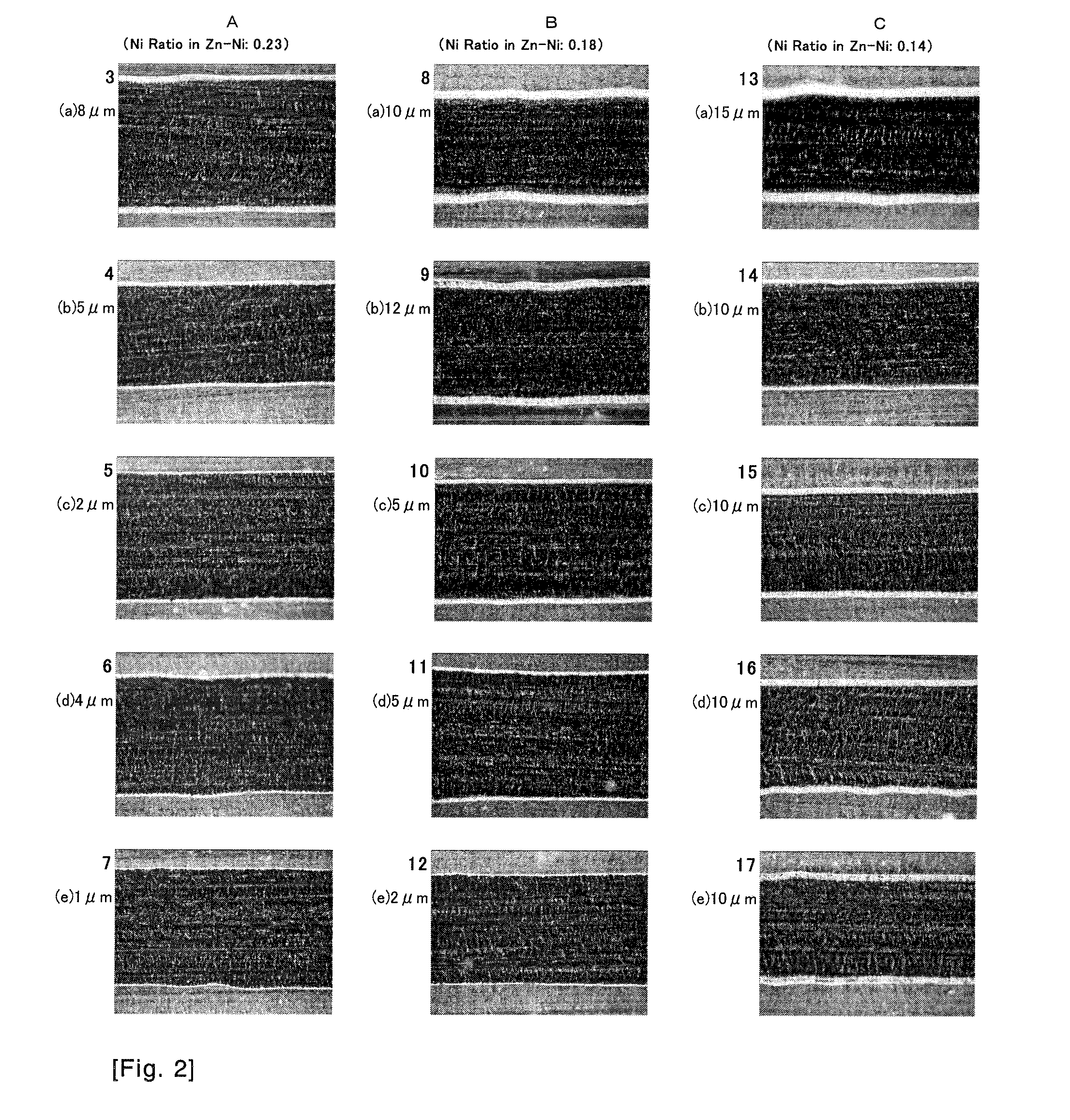
example 1
Deposited Mass of Zn—Ni Alloy: 300 μg / dm2, Ni ratio: 0.23, Provided that the Ni Content is 69 μg / dm2
example 2
Deposited Mass of Zn—Ni Alloy: 371 μg / dm2, Ni Ratio: 0.23, Provided that the Ni Content is 85 μg / dm2
example 3
Deposited Mass of Zn—Ni Alloy: 470 μg / dm2, Ni Ratio: 0.23, Provided that the Ni Content is 108 μg / dm2
Login to View More PUM
| Property | Measurement | Unit |
|---|---|---|
| Length | aaaaa | aaaaa |
| Length | aaaaa | aaaaa |
| Temperature | aaaaa | aaaaa |
Abstract
Provided is a copper foil for printed circuit comprising a roughened layer on a surface of a copper foil by way of copper-cobalt-nickel alloy plating, a cobalt-nickel alloy plated layer formed on the roughened layer, and a zinc-nickel alloy plated layer formed on the cobalt-nickel alloy plated layer, wherein the total amount of the zinc-nickel alloy plated layer is 150 to 500 μg / dm2, the lower limit of the nickel ratio in the alloy layer is 0.16, the upper limit thereof is 0.40, and the nickel content is 50 μg / dm2 or more.With the development of electronic equipment, the miniaturization and high integration of semiconductor devices have advanced further. This tendency has led to a demand for the adoption of a higher temperature in treatment in a production process of printed circuits and has led to heat generation during the use of electronic equipment after the productization. The present invention provides a technique that, even under these circumstances, the adhesive strength between a copper foil and a resin base material does not decrease and the penetration into a circuit edge part can be effectively prevented when performing the soft etching of a copper foil circuit.
Description
TECHNICAL FIELD[0001]The present invention relates to a copper foil for printed circuit and a copper-clad laminate, and in particular relates to a copper foil for printed circuit and a copper-clad laminate having alkali etching properties as well as favorable thermal peeling strength and thermal oxidation resistance as a result of performing roughening treatment on the surface of the copper foil by way of copper-cobalt-nickel alloy plating and thereafter forming a cobalt-nickel alloy plated layer and a zinc-nickel alloy plated layer. More specifically, the present invention relates to a copper foil for printed circuit and a copper-clad laminate capable of inhibiting the penetration of the etching solution into the base of the circuit when performing soft etching after forming the circuit. The copper foil of the present invention can be suitably applied, for example, to a fine pattern printed circuit and a magnetic head FPC (Flexible Printed Circuit).BACKGROUND ART[0002]Copper and co...
Claims
Login to View More Application Information
Patent Timeline
 IPC IPC(8): H05K1/09H01B5/00
CPCC25D3/56C23C28/3455C25D3/565C25D3/58C25D5/12C25D5/14C25D5/16C25D5/48C25D5/56C25D7/0614C25D9/08H05K3/067H05K3/384H05K2201/0355H05K2203/0307H05K2203/0723C23C28/021C23C28/028C23C28/321C23C28/325C23C28/345C25D3/562C25D5/627C25D5/605
InventorHIGUCHI, NAOKI
OwnerJX NIPPON MINING& METALS CORP