Induced power transmission circuit

a power transmission circuit and induction technology, applied in the direction of transformers, multiple-port networks, inductances, etc., can solve the problems of low power transfer efficiency, waste of electric power supplied from the power supply circuit, etc., and achieve the effect of efficient power transfer

Active Publication Date: 2010-08-26
KIKUCHI HIDEO
View PDF0 Cites 247 Cited by
  • Summary
  • Abstract
  • Description
  • Claims
  • Application Information

AI Technical Summary

Benefits of technology

[0029]The inductive electric power transfer circuit according to present invention transfers electric power at the angular frequency ω from the transmitter antenna, which is connected to the power supply circuit, to the receiver antenna through space. Power is transferred efficiently from the power supply circuit to the load circuit by decreasing the impedances of the power supply circ

Problems solved by technology

However, there is a deficiency that their power transfer efficiency according to patent document 1 becomes low when the distance between the primary winding and the secondary winding is enlarged, then mutual inductances M between the primary winding and the secondary winding becom

Method used


Image

  • Induced power transmission circuit
  • Induced power transmission circuit
  • Induced power transmission circuit

Examples


first embodiment

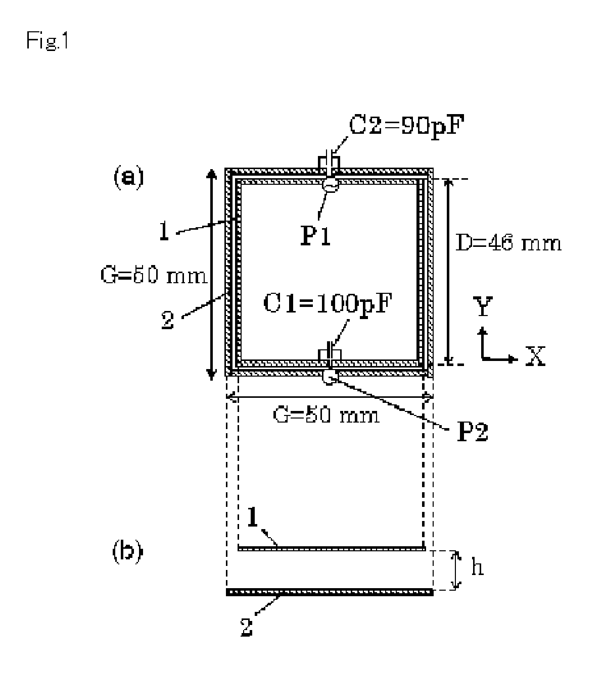
[0137]In the first embodiment of the inductive electric power transfer circuit is composed of receiver antenna buried inside of a body, and the transmitter antenna out of the body, so that it transfers the electric power between them through the skin of the body. The first embodiment is described using FIG. 1 to FIG. 12.

[0138]In FIG. 1, transmitter antenna 1 is copper ribbon wiring whose width is 1 mm and thickness is 50 μm, and has the shape of one turn coil on the plane whose diameter D is 46 mm. For instance, the transmitter antenna 1 is formed on the polyimide film of 25 μm in thickness. The receiver antenna 2 can be made in a shape of coil, the coil diameter G is 50 mm, and the antenna wiring is covered with polyimide layer of 25 μm in thickness, so that it can be buried inside of a body by an operation. The terminal Port 1 (P1) of the power supply circuit 3 which feeds power is connected in series with the transmitter antenna 1 at the middle of the antenna wiring. A feeder cab...

second embodiment

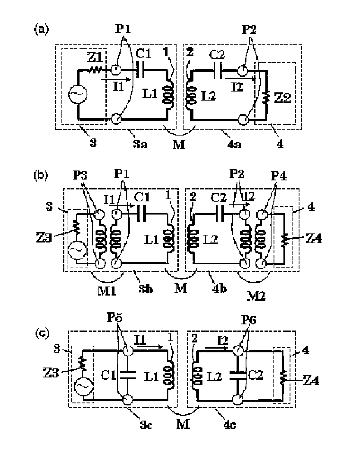
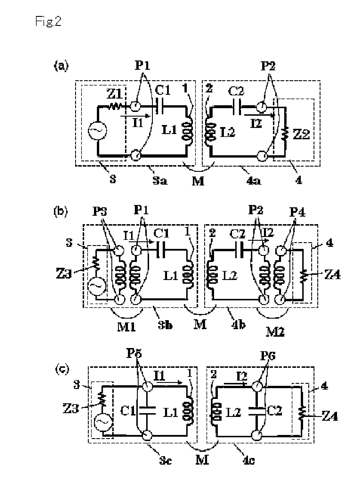
[0169]The second embodiment composes the inductive electric power transfer circuit that supplies the power from the transmitter antenna 1 in vitro to the receiver antenna 2 in vivo through the outer skin. The inductive electric power transfer circuit is adapted to the circumstances that the position of the transmitter antenna 1 and receiver antenna 2 are not steady and coefficient of coupling k of electromagnetic induction changes, to keep the stability of power transfer. In this embodiment, the inductive electric power transfer circuit is composed of the transmitter antenna 1 and the receiver antenna 2 in FIG. 7, and the antennas are operated at the second type resonance of the principle of the present invention.

[0170]FIG. 13(a) shows the power transfer efficiency (%) as a function of impedance Z, which is represented by the non-dimensional parameter Z / (2πfL), of power supply circuit 3 and load circuit 4 when the antenna-spacing h between transmitter antenna 1 and receiver antenna ...

third embodiment

[0177]In the third embodiment, the inductive electric power transfer circuit transfers electric power through a wall of a house. The inductive electric power transfer circuit has many turned spiral wiring for antennas, so that induced resistance of the antenna is great and is close to the characteristic impedance of the feeder, which connects the power supply circuit 3 to the transmitter antenna 1 and transfers power. This inductive electric power transfer circuit is operated at the third type resonance of the principle of the present invention. FIG. 14(a) shows a front view of the transmitter antenna 1 and the receiver antenna 2 which are in the inductive-electric-power-transfer-circuit for the third embodiment. FIG. 14(b) shows a side view of them. Similarly to the first embodiment, the power supply circuit 3 is connected to the transmitter antenna 1 and the load circuit 4 is connected to the receiver antenna 2. In FIG. 14, the transmitter antenna 1 is composed as follows. The ant...


PUM


Abstract

To provide an induced power transmission circuit that transmits, from a transmission antenna (1) connected to a power supply circuit, an AC power having an angular frequency ω to a spaced reception antenna (2) with an excellent efficiency, thereby transmitting it to a load circuit. The induced power transmission circuit comprises a circuit the two ends of which are coupled by a capacitor (C1) and in which the power supply circuit is connected in series to a midway port (1) (P1) of the transmission antenna (1) having an effective self-inductance L1; and a circuit the two ends of which are coupled by a capacitor (C2) and in which the load circuit is connected in series to a midway port (2) (P2) of the reception antenna (2) having an effective self-inductance L2; wherein for a coupling coefficient k of the electromagnetic induction between the antennas and for a phase angle β having an arbitrary value, the angular frequency ω is set to the square root of the reciprocal of a value of L2×C2×(1+k*cos (β)), the output impedance of the power supply circuit is set to approximately kωL1*sin (β), and the input impedance of the load circuit is set to approximately kωL2*sin (β). There is also provided an impedance converting circuit that converts the circuit impedances.

Description

TECHNICAL FIELD[0001]This invention concerns the inductive electric power transfer circuit in which the electric power is transferred through air space with wireless inducting means.BACKGROUND[0002]In patent document 1, an inductive electric power transfer circuit for an electric vehicle is proposed. That transfers electric power from a primary winding of a power supply facility to a secondary winding of a powered device of an electrical vehicle. Since it has no contact points, the inductive electric power transfer circuit has an advantage that is free from lose contact problems for electric terminals. The inductive electric power transfer circuit transfers power by electromagnetic induction on the secondary winding of the powered device with electromagnetic field generated by current on the primary winding of the power supply facility. A capacitor is connected between both ends of the secondary winding, and a resonant circuit is constructed with the secondary winding and the capaci...

Claims


Application Information

Patent Timeline
IPC IPC(8): H02J17/00
CPCH01Q1/248H03H7/38H02J17/00H02J5/005H02J50/12H02J50/90H02J50/40
Inventor KIKUCHI, HIDEO
Owner KIKUCHI HIDEO
Why Eureka
Try Eureka