

Symmetric load delay cell oscillator
- Summary
- Abstract
- Description
- Claims
- Application Information
AI Technical Summary
Benefits of technology
Problems solved by technology
Method used
Image

Examples
Embodiment Construction
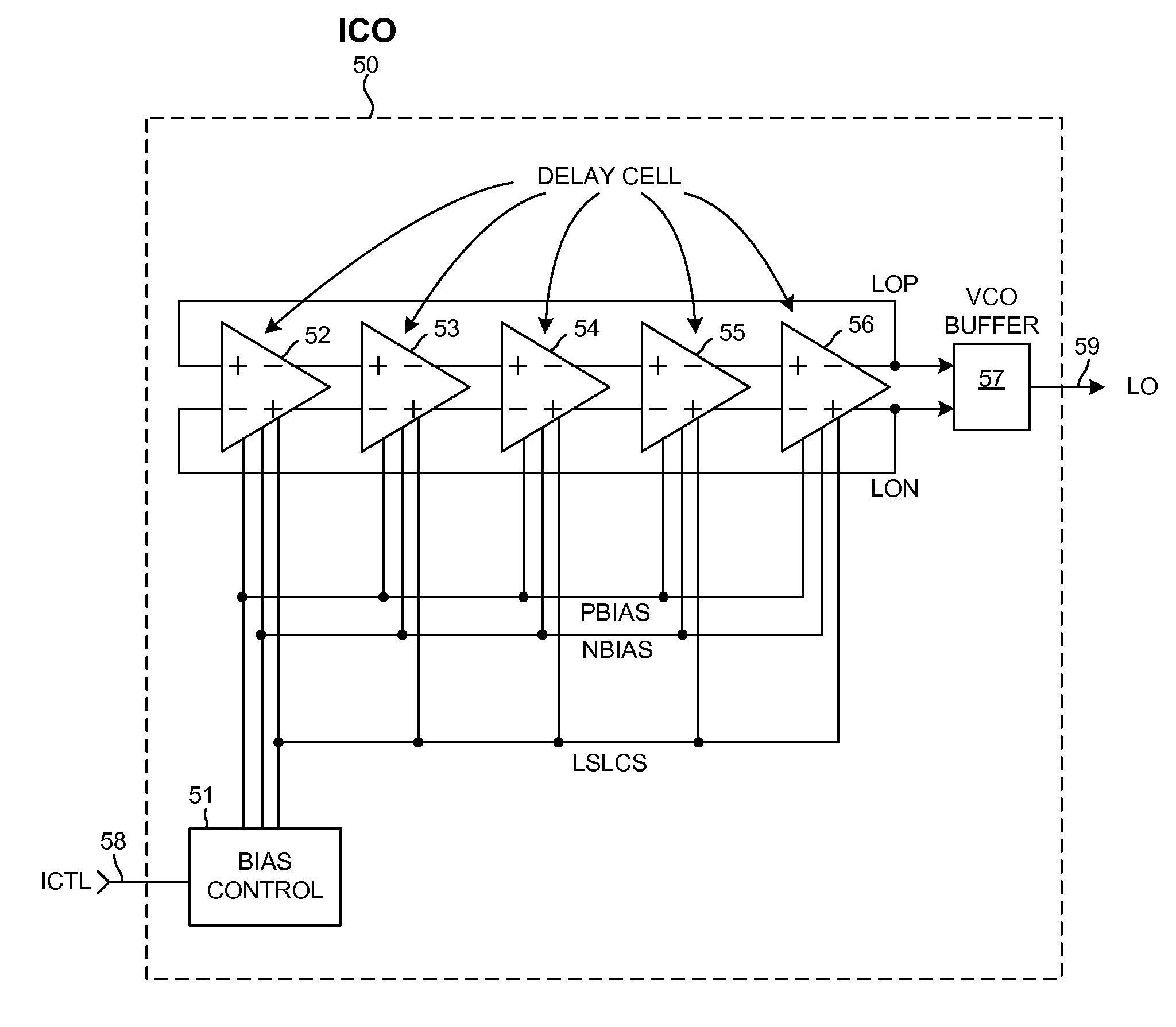
[0047]FIG. 9 is a simplified diagram of one example of a Current-Controlled Oscillator (ICO) 50 in accordance with one novel aspect. ICO 50 may, for example, see use in a Phase-Locked Loop (PLL) within a local oscillator of a radio receiver or a radio transmitter. ICO 50 includes a bias control circuit 51, five delay cell stages 52-56 coupled together in a ring, and a VCO buffer 57. Increasing an input control current ICTL received on input lead 58 results in a corresponding increase in the frequency of oscillation (FOSC) of an output signal LO on output lead 59. Unlike the conventional circuit of FIG. 3, the input control current to output frequency relationship is substantially linear over a relatively wide frequency tuning range.
[0048]FIG. 10 is a more detailed diagram of delay cell 52 of FIG. 9. All delay cells 52-56 are of identical construction. Delay cell 52 includes a first symmetric load 60, a second symmetric load 61, a tail current source transistor 62, a first switching ...
PUM
 Abstract
Description
Claims
Application Information