Electromagnetic wave reflecting member

a technology of electromagnetic waves and reflective members, applied in the field of electromagnetic waves reflecting members, can solve the problems of cholesteric liquid, high cost of selectively reflective members, high cost of chemically synthesized and thus high cost, and achieve the effect of high efficiency and cost-effectiveness

Inactive Publication Date: 2010-08-26
DAI NIPPON PRINTING CO LTD
View PDF8 Cites 11 Cited by
  • Summary
  • Abstract
  • Description
  • Claims
  • Application Information

AI Technical Summary

Benefits of technology

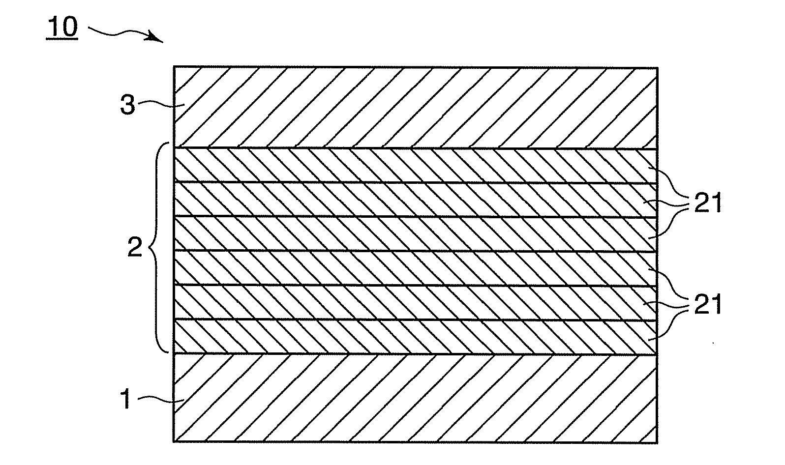
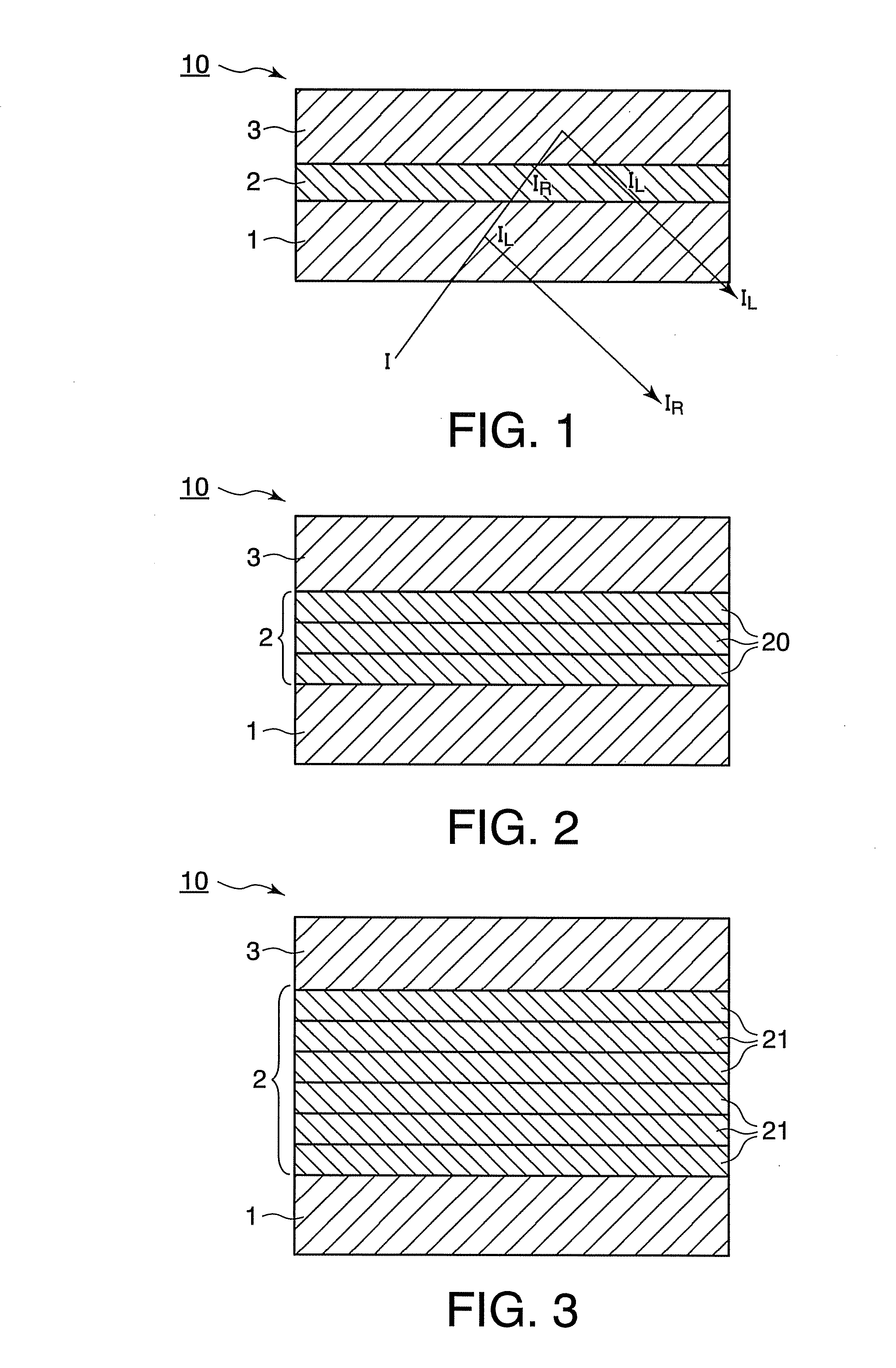
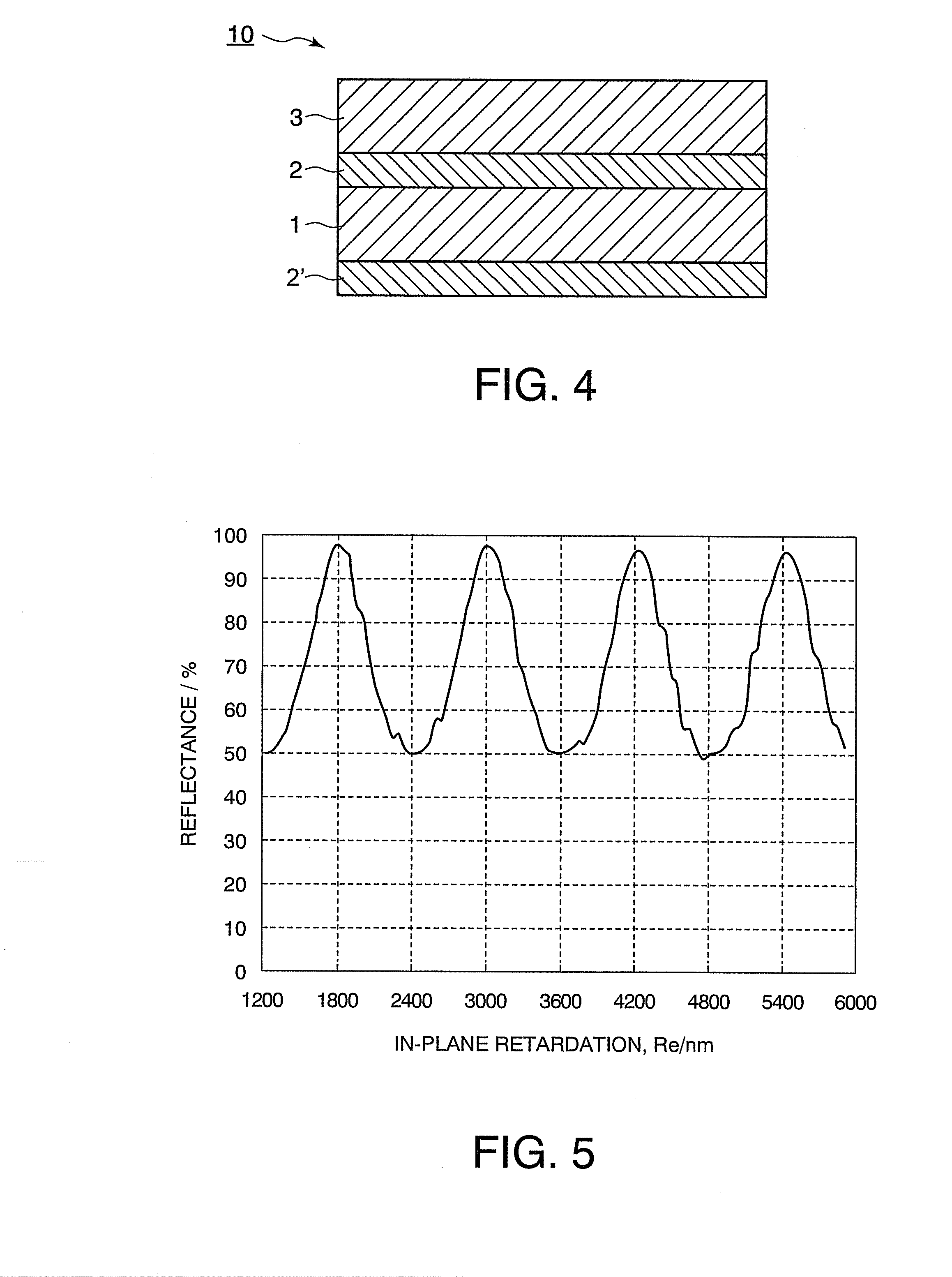
[0024]According to the present invention, the phase difference layer held between the first and second selectively reflective layers that reflect only a clockwise or counterclockwise polarized light component with wavelength λ in electromagnetic waves has an average retardation satisfying the following relationship: Re={(2n+1)/2±0.2}×λ. Accordingly, for example, when a selectively reflective layer that selectively reflects near-infrared light with a wavelength of 1200 nm is used, the average retardation Re of the phase difference layer is 1800 nm at n=1, 3000 nm at n=2, 4200 nm at n=3, and 5400 nm at n=4. Therefore, eve

Problems solved by technology

Cholesteric liquid crystals having a counterclockwise spiral pitch, however, hardly exist in nature, and thus should be chemically synthesized and thus are highly expensive.
Accordingly, this leads to an increase in cost of selectively reflective members comprising a cholesteric liquid crystal film, which reflects a counterclockwise circularly polarized light component, and a cholesteric liquid crystal film, which reflects a clockwise circularly polarized light component, stacked on top of each other.
For this reason, the production of the above laminates on a commercial scale at low cost is difficult.
The casting method,

Method used


Image

  • Electromagnetic wave reflecting member
  • Electromagnetic wave reflecting member
  • Electromagnetic wave reflecting member

Examples


example 1

Provision of Phase Difference Layer

[0068]A biaxially stretched film of polyethylene terephthalate (Lumirror (registered trademark) U35, manufactured by Toray Industries, Inc.) was provided as a phase difference layer. The thickness of the film was 188 μm. The average retardation was measured with KOBRA-WX100 / IR manufactured by Oji Scientific Instruments (measuring angle 0 degree, wavelength 1200 nm) and was found to be about 4083 nm. Accordingly, the biaxially stretched film satisfied formula (1) wherein n=3. Further, the in-plane distribution of the retardation in a transverse direction (TD) of the biaxially stretched film and the in-plane distribution of the retardation in a machine direction (MD) of the biaxially stretched film were as shown in FIGS. 6 and 7.

[0069]A solution of 97.2 parts of liquid crystalline monomer molecules (Paliocolor (registered trademark) LC1057, manufactured by BASF) containing a polymerizable acrylate at both ends thereof and having a spacer between a me...

example 2

[0072]The biaxially stretched film as used in Example 1 was used as a phase difference layer. A selectively reflective layer was formed on one side of the biaxially stretched film in the same manner as in Example 1. Subsequently, the selectively reflective layer was also formed on the other side of the biaxially stretched film in the same manner as described just above to prepare an electromagnetic wave reflecting member. The reflecting properties of the electromagnetic wave reflecting member were measured at a regular reflection angle of 5 degrees with a spectrophotometer and were found to be the same as those shown in FIG. 8 (a solid line).

example 3

[0073]A biaxially stretched film of polyethylene terephthalate (Lumirror (registered trademark) T60, manufactured by Toray Industries, Inc.) was used, instead of the biaxially stretched film used in Example 1, as a phase difference layer. The thickness of the film was 38 μm. The average retardation was measured with KOBRA-WX100 / IR manufactured by Oji Scientific Instruments (measuring angle 0 degree, wavelength 1200 nm) and was found to be about 1944 nm. Accordingly, the biaxially stretched film satisfied formula (1) wherein n=1. Further, the in-plane distribution of the retardation in a transverse direction (TD) of the biaxially stretched film and the in-plane distribution of the retardation in a machine direction (MD) of the biaxially stretched film were as shown in FIGS. 9 and 10.

[0074]An electromagnetic wave reflecting member was prepared by forming a selectively reflective layer on both sides of the biaxially stretched film in the same manner as in Example 2. The reflecting prop...


PUM


Abstract

Disclosed is a selectively reflective member which can uniformly reflect only a desired wavelength with high efficiency even in a large area and, at the same time, is highly cost effective. Specifically, there is provided an electromagnetic wave reflecting member that reflects electromagnetic waves with a specific wavelength, the electromagnetic wave reflecting member comprising a first selectively reflective layer that reflects only a clockwise or counterclockwise circularly polarized light component with wavelength λ in incident electromagnetic waves, a phase difference layer, and a second selectively reflective layer that reflects only a clockwise or counterclockwise circularly polarized light component with wavelength λ, provided in that order, the phase difference layer having a retardation satisfying the following equation:
Re={(2n+1)/2±0.2}×λ
wherein Re represents average retardation; λ represents wavelength; and n is an integer of 1 or more.

Description

BACKGROUND OF THE INVENTION[0001]1. Field of the Invention[0002]The present invention relates to an electromagnetic wave reflecting member and more specifically to an electromagnetic wave reflecting member that can efficiently and uniformly reflect electromagnetic waves with a specific wavelength falling within a visible to far-infrared light wavelength range.[0003]2. Background Art[0004]Selectively reflective members using cholesteric liquid crystals are known as a member that can selectively reflect a light component with a desired wavelength in a visible light to heat radiation wavelength range. These selectively reflective members can selectively reflect only light (electromagnetic waves) with a desired wavelength and thus are expected to be used, for example, as heat radiation reflecting films or light transparent and heat insulating films that are transparent to visible light and reflect only a heat radiation. In the cholesteric liquid crystal which can realize selective refle...

Claims


Application Information

Patent Timeline
IPC IPC(8): G02B5/30
CPCG02B5/26G02B27/288G02B5/286G02B5/3083
Inventor KURODA, TAKASHIHAMADA, SATORUKASHIMA, KEIJI
Owner DAI NIPPON PRINTING CO LTD
Why Eureka
Try Eureka