
Radio frequency (RF) power limiter and associated methods

a power limiter and receiver technology, applied in the field of radio frequency (re) communication, can solve the problems of undesired reflection and attenuation of rf signal, undesired non-linear rf signal harmonic generation, and circuit components of the receiving system susceptible to burnou

Inactive Publication Date: 2010-08-26
HARRIS CORP
View PDF10 Cites 8 Cited by
  • Summary
  • Abstract
  • Description
  • Claims
  • Application Information

AI Technical Summary

Benefits of technology

[0010]In view of the foregoing background, it is therefore an object of the present invention to provid

Problems solved by technology

The basic function of a power limiter is to protect sensitive electronics from RE power above a predetermined value because some devices can be permanently damaged when subjected to an electrical field of a sufficient magnitude.
In such an environment, high RE input signal levels provided by leakage from the radar's transmitter or from hostile jammers for example, pose a threat to those circuit components of a receiving system which are susceptible to burn out as a result of a high incident power level.
For example, the LNA used in the RF front end of a radar receiver generally includes at least one field effect transistor which is susceptible to damage due to high incident power levels.
In either of these configurations, the finite conductance characteristics of the PIN diode causes an undesired reflection and attenuation of the RF signal and undesired non-linear RF signal harmonic generation, that is, during normal operation when the power limiter need not limit power.
While operating in a power limiting mode however, the PIN diodes are placed in a forward biased conductive state, and as a result, the limiter presents a very high insertion loss characteristic to input power signals.
Some LNAs can handle high (e.g. +20 dBm) input signal power, but not for very long, as performance degrades with the extended duration of the high power input signals.

Method used


Image

  • Radio frequency (RF) power limiter and associated methods
  • Radio frequency (RF) power limiter and associated methods
  • Radio frequency (RF) power limiter and associated methods

Examples


Embodiment Construction

[0025]The present invention will now be described more fully hereinafter with reference to the accompanying drawings, in which preferred embodiments of the invention are shown. This invention may, however, be embodied in many different forms and should not be construed as limited to the embodiments set forth herein. Rather, these embodiments are provided so that this disclosure will be thorough and complete, and will fully convey the scope of the invention to those skilled in the art. Like numbers refer to like elements throughout.

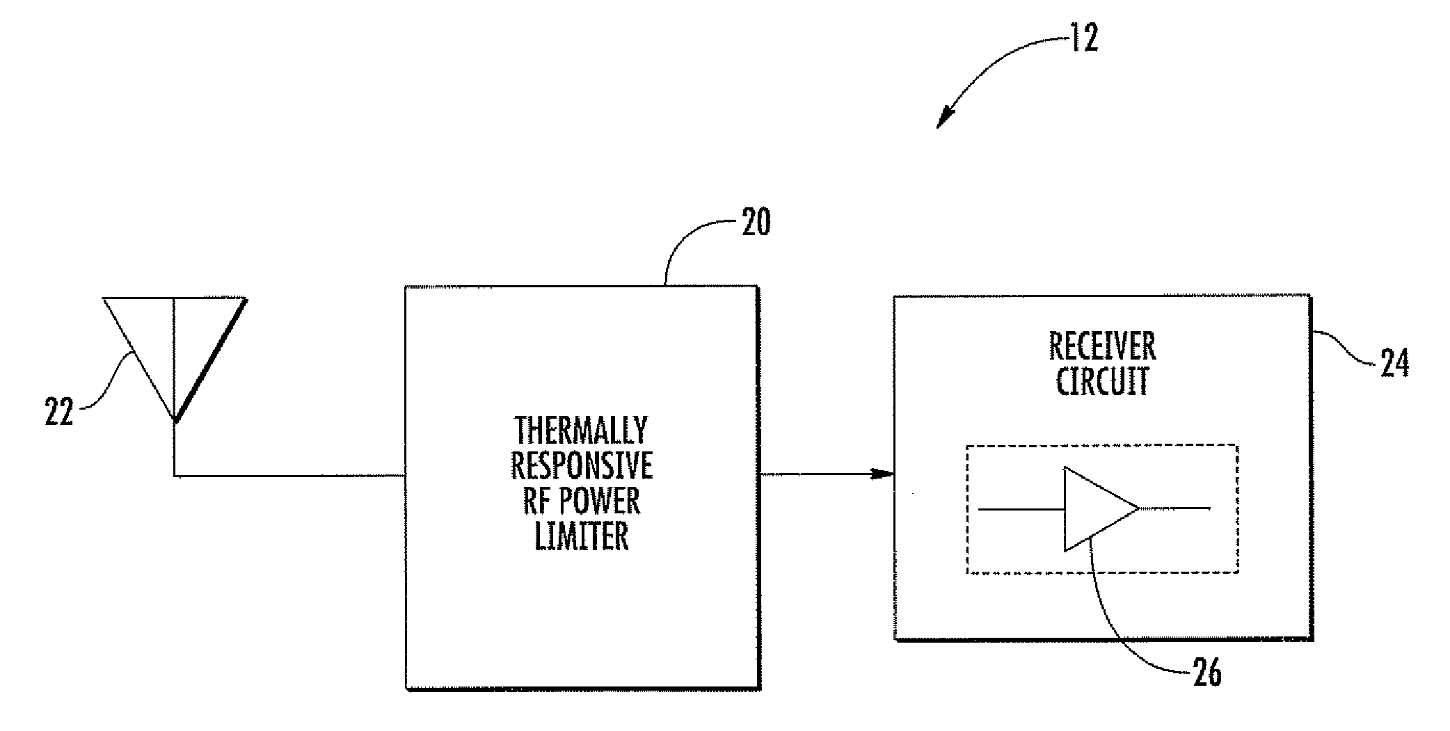
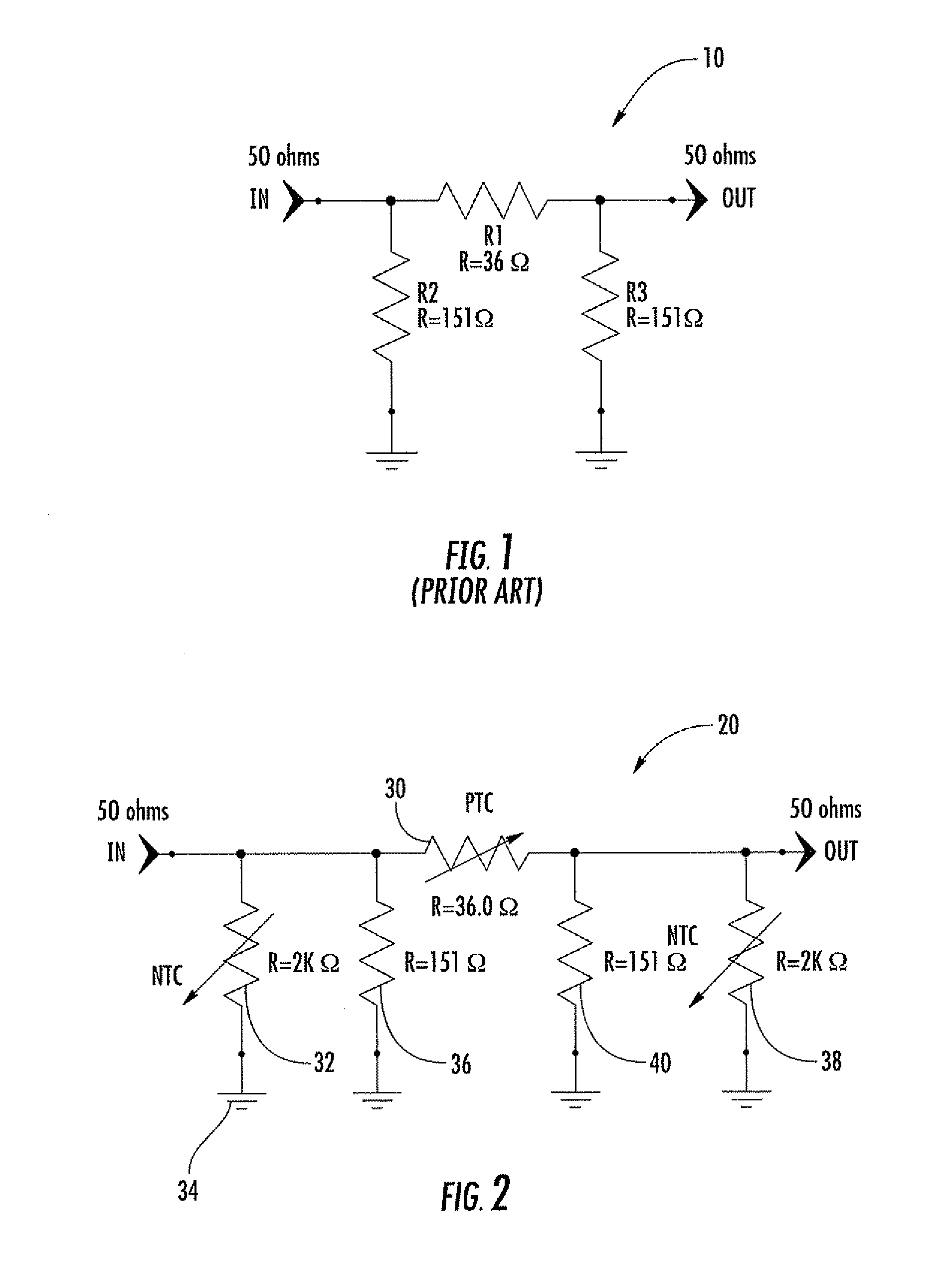
[0026]Referring initially to FIG. 1, a common attenuator circuit 10, known as the “pi attenuator network,” is illustrated. An attenuator is an electronic device that reduces the amplitude or power of a signal without appreciably distorting its waveform. An attenuator is effectively the opposite of an amplifier, though the two work by different methods. While an amplifier provides gain, an attenuator provides loss, or gain less than 1. Perhaps the most comm...


PUM


Abstract

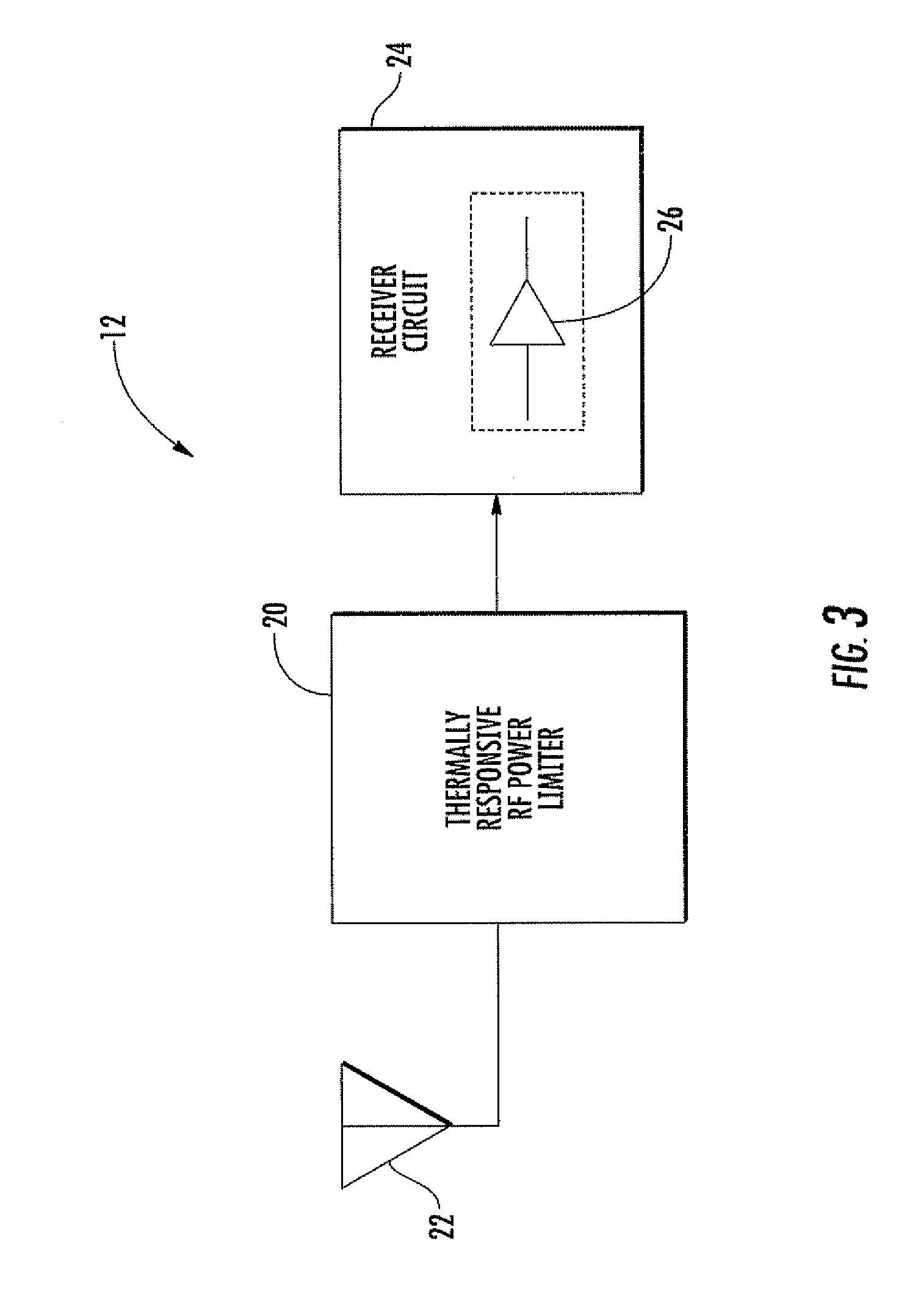
A resistive radio frequency (RF) signal power limiter is for connection between an antenna and a receiver circuit in an RF receiver system. The receiver circuit may include a low noise amplifier (LNA). The resistive RF signal power limiter may include at least one positive temperature coefficient (PTC) thermistor connected in series, and at least one negative temperature coefficient (NTC) thermistor connected in shunt between the at least one PTC thermistor and a reference voltage.

Description

FIELD OF THE INVENTION[0001]The present invention relates to the field of radio frequency (RE) communications, and, more particularly, to a power limiter in an RF receiver and related methods.BACKGROUND OF THE INVENTION[0002]Power limiters are commonly used in a variety of communication systems. The basic function of a power limiter is to protect sensitive electronics from RE power above a predetermined value because some devices can be permanently damaged when subjected to an electrical field of a sufficient magnitude. In REF receiving systems, a typical receiver includes a so-called “RF front end” which generally has an antenna coupled to a low noise amplifier (LNA). The amplifier generally is fed to an RF mixer which, in turn, feeds a detector circuit.[0003]It is also known in the art that RF receivers, such as those used in radar systems, for example, typically operate in environments which pose a number of electromagnetic hazards. In such an environment, high RE input signal le...

Claims


Application Information

Patent Timeline
IPC IPC(8): H04B1/06G05B23/02
CPCH03F1/52H04B1/18H03G11/002H03G1/0041H04B1/10H03H7/25H02H9/02
Inventor MAST, ALAN WILLIAM
Owner HARRIS CORP
Learn More