Intervertebral milling instrument

a milling instrument and intervertebral technology, applied in the field of improved surgical instruments, can solve the problems of loosening of the spacer element, significant increase in the risk of inadequate spacer element attachment, and unfavorable osseointegration attachment of the cfc layer to the spacer

Inactive Publication Date: 2010-08-26
THE GOVERNMENT OF THE UNITED STATES OF AMERICA AS REPRESENTED BY THE DEPT OF VETERANS AFFAIRS +1
View PDF6 Cites 25 Cited by
  • Summary
  • Abstract
  • Description
  • Claims
  • Application Information

AI Technical Summary

Benefits of technology

[0007]In accordance with the invention, an intervertebral milling instrument is provided for closely controlled removal of a thin layer of calcified fibrous cartilage (CFC) from adjacent vertebrae during spinal fusion or spacer element implantation surgery. The milling instrument comprises a guide housing having a closely predetermined thickness dimension sized to fit into the specific and unique patient intervertebral space following surgical removal of natural cartilage therefrom. A grinding wheel is rotatably carried within the guide housing in a manner for closely controlled and limited exposure of the grin

Problems solved by technology

However, such CFC layer is not conducive to secure osseointegration attachment to a spacer element installed into the intervertebral space following removal of the natural cartilage.
That is, the CFC layer exhibits a marked inability to resist bone remodeling or attachment ingrowth thereby resulting in a significant increase in the risk of inadequate spacer element attachment and resultant undesirable post-surgical loosening of the spacer element.
While such prior art devices may or may not have recognized the need to remove the thin CFC layer from the patient bone in order

Method used


Image

  • Intervertebral milling instrument
  • Intervertebral milling instrument
  • Intervertebral milling instrument

Examples


Embodiment Construction

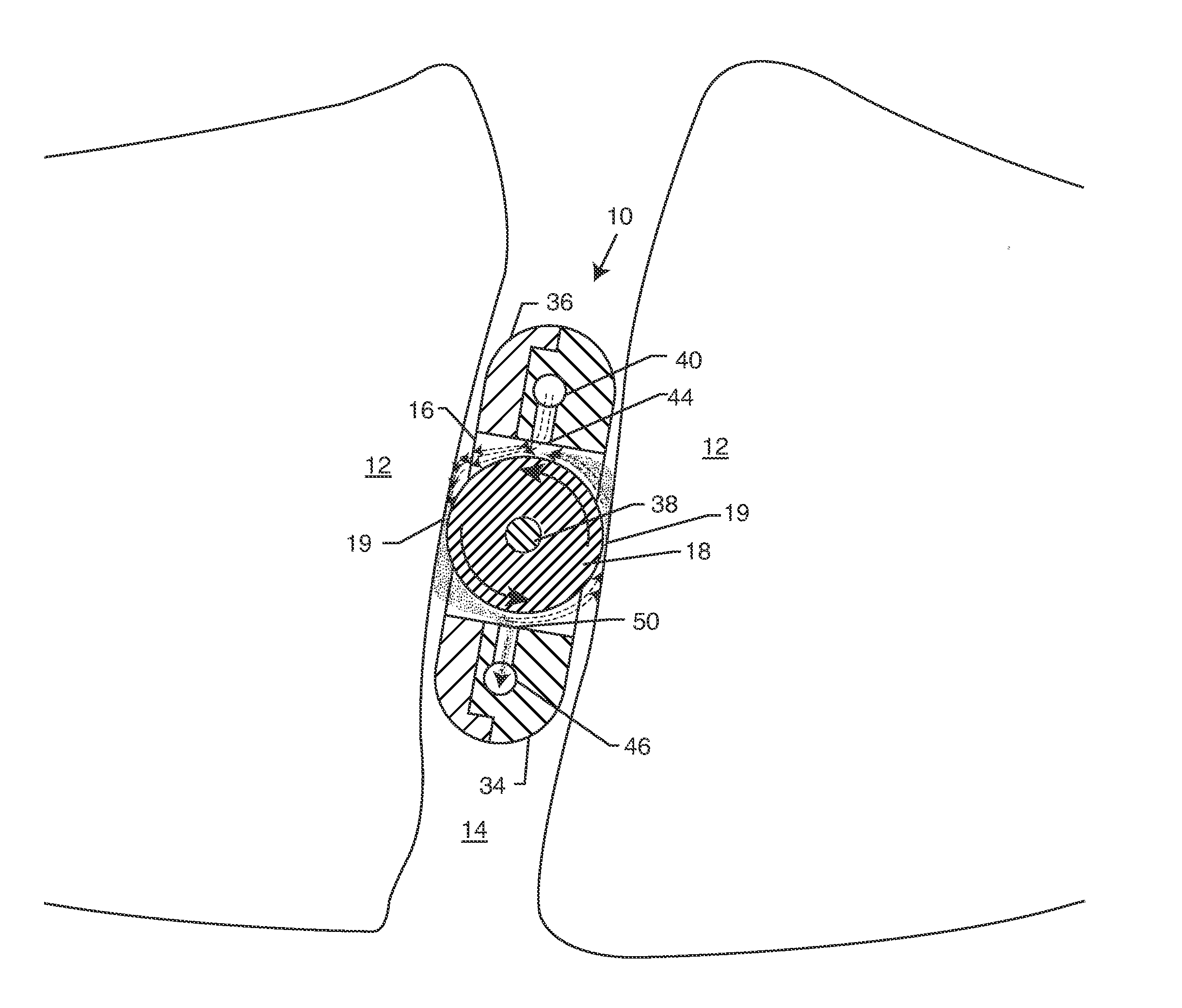
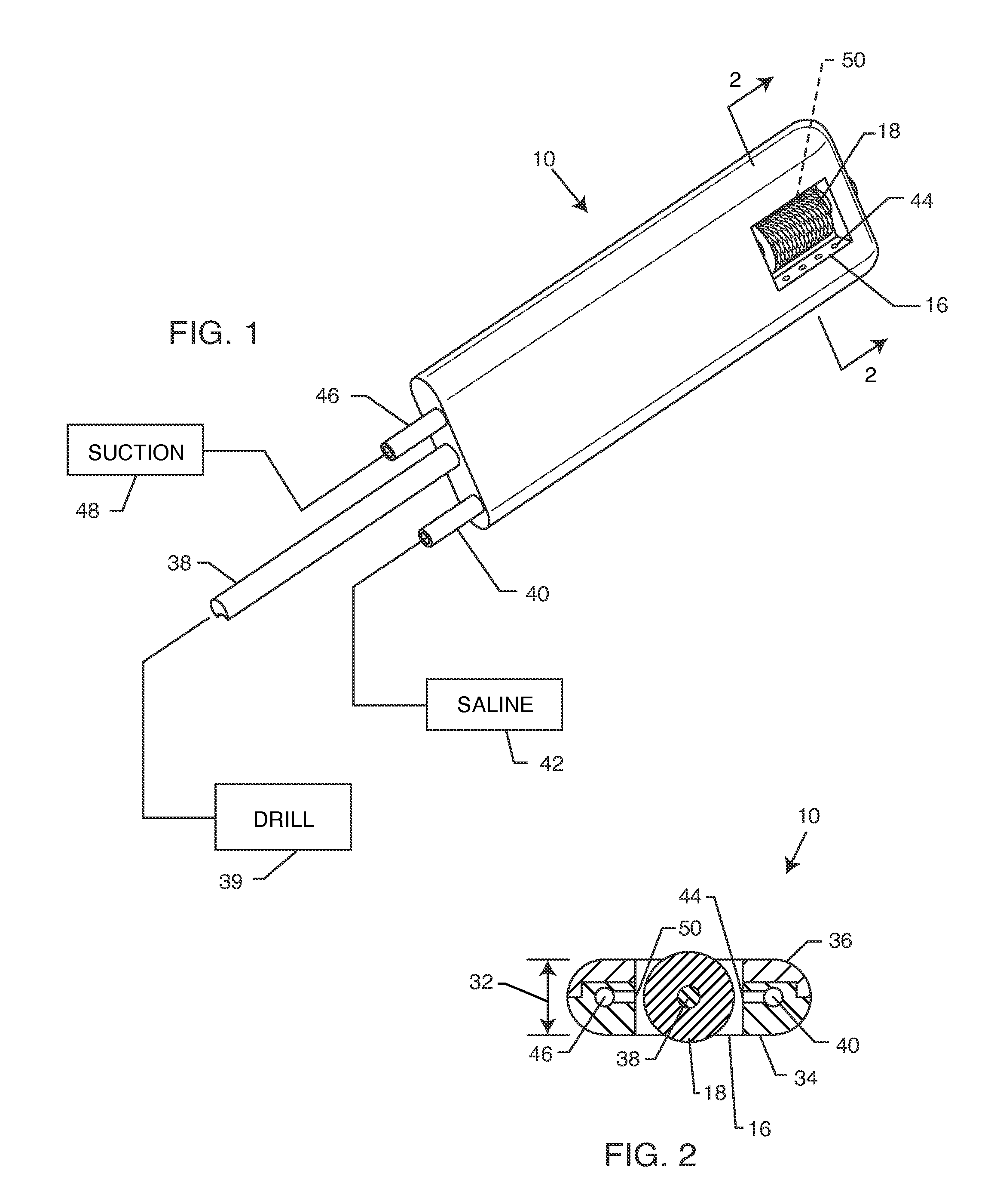
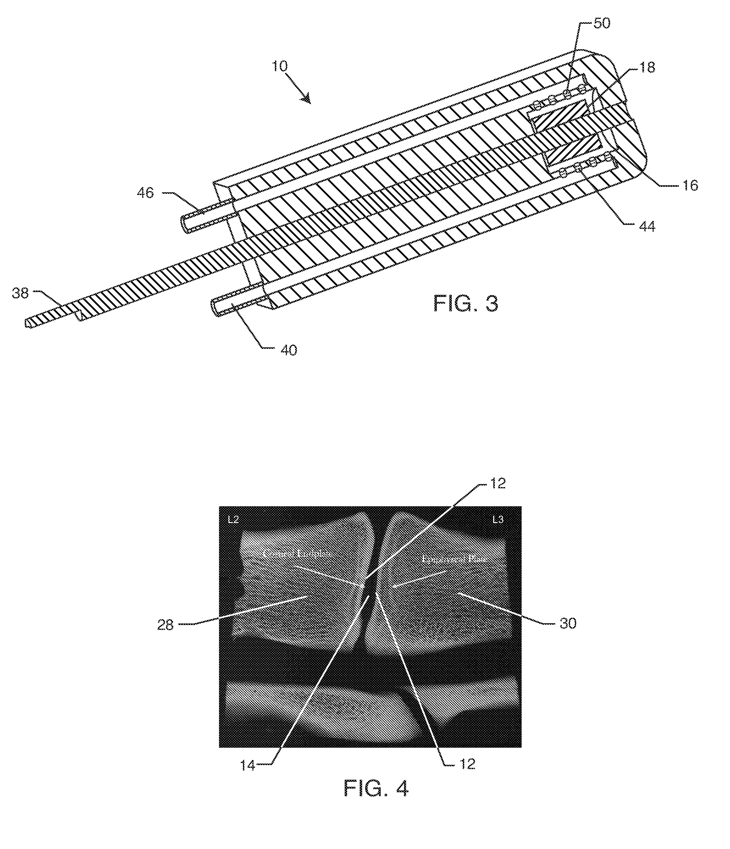
[0025]As shown in the exemplary drawings, a milling instrument referred to generally by the reference numeral 10 is provided for grinding or shaving in a closely controlled manner a thin layer from the cortical bone endplates 12 (FIG. 10) lining an intervertebral space 14 in the course of spinal fusion surgery or the like. The milling instrument 10 comprises a guide housing 16 having a thickness dimension selected to fit with close tolerance into the intervertebral space, in combination with a grinding or milling wheel 18 exposed and protruding a short distance beyond the opposed side faces of the guide housing 16 for engaging and contacting the adjacent cortical endplates 12 lining the intervertebral space 14. The grinding wheel 18 thereby removes a thin layer such as a thin layer of calcified fibrous cartilage 19 (CFC) from the cortical endplates 12 in a controlled manner, for achieving improved fusion ingrowth fixation with a spacer element 20 (FIG. 9) implanted subsequently into...


PUM


Abstract

An intervertebral milling instrument for removing calcified fibrous cartilage (CFC) from adjacent vertebrae during spinal fusion or spacer implantation surgery. The milling instrument includes a grinding wheel carried within a guide housing sized to fit closely into the intervertebral space, and to expose the grinding wheel on opposite sides thereof for controlled removal of CFC layers from adjacent cortical end plates. The grinding wheel is rotatably driven as by attachment to a surgical drill, preferably to include saline supply to and suction removal from the grinding site. The controlled removal of CFC layers is limited to about 100 to about 250 microns, thereby avoiding exposing the cortical end plates without excessive bone removal. The instrument is conveniently provided in a kit having multiple guide housings and associated grinding wheels of different sizes to fit into different intervertebral spaces.

Description

BACKGROUND OF THE INVENTION[0001]This invention relates generally to an improved surgical instrument for controlled milling or shaving to remove calcified fibrous cartilage (CFC) from adjacent vertebrae in the course of spinal surgery such as fusion or spacer implantation surgery. The improved instrument comprises a compact guide housing having a size selected to fit closely into the intervertebral space, wherein the guide housing carries a small grinding wheel that is partially exposed and protrudes a short distance beyond the opposite side faces of the guide housing for engaging and removing thin CFC layers from the cortical endplates of adjacent vertebrae in a closely controlled manner. Excessive bone removal and resultant undesirable exposure of softer cancellous bone is thereby avoided. In a preferred form, the surgical instrument is provided in a kit comprising multiple different guide housings of selected different widths, with the surgeon selecting a specific instrument guid...

Claims


Application Information

Patent Timeline
IPC IPC(8): A61B17/00
CPCA61B17/1644A61B17/1671A61B2217/007A61B2217/005A61B2017/1651
Inventor BLOEBAUM, ROY D.JEYAPALINA, SUJEEVINITANNER, AMIE M.BOWMAN, JULIAN C.
Owner THE GOVERNMENT OF THE UNITED STATES OF AMERICA AS REPRESENTED BY THE DEPT OF VETERANS AFFAIRS
Why Eureka
Try Eureka