
High temperature roll

a high-temperature roll and rolling technology, applied in the field of rolling, can solve the problems of reducing the thermal expansion disparity of the entire roll, affecting the quality of the glass roll, so as to reduce the thermal expansion disparity and reduce the content of the shot fiber

Inactive Publication Date: 2010-09-02
VESUVIUS CRUCIBLE CO
View PDF18 Cites 13 Cited by
  • Summary
  • Abstract
  • Description
  • Claims
  • Application Information

AI Technical Summary

Benefits of technology

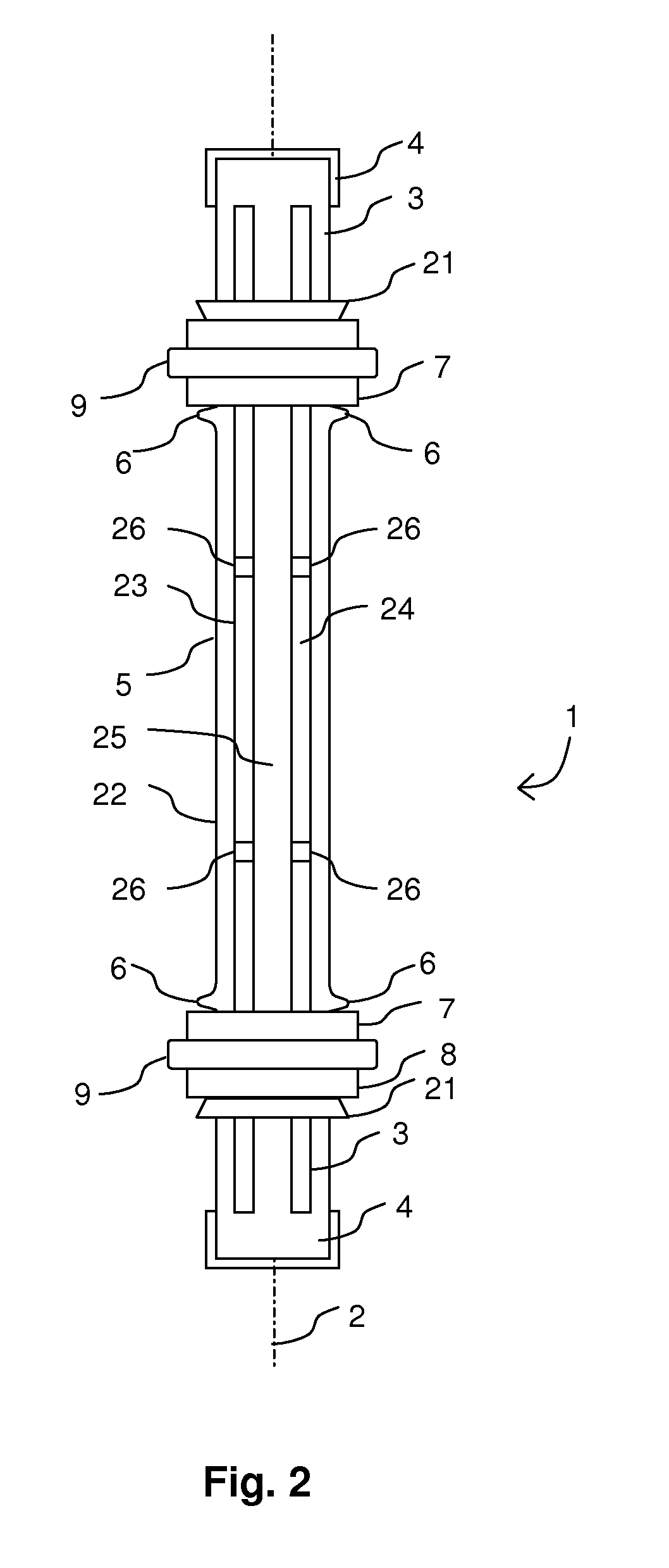
[0011]In another aspect, the pulling roll includes a hollow body that is substantially cylindrical. The body comprises fused silica or other non-dusting, rigid refractory ceramic. The cylinder includes a longitudinal axis, an outer surface, an inner surface, and opposite ends. End caps are fixedly secured to the ends and are capable of connecting with a driving mechanism that rotates the roll. Pulling flats are fixed on the outer surface by retainers comprising split rings. A metal rod extends through the hollow cylinder and is secured to the cylinder by compressible supports. The supports accommodate differences in thermal expansion between the metal rod and ceramic cylinder so that thermal expansion of the rod does not exert an undue tensile stress on the body. The rod provides a fail-safe in the event the body breaks.
[0014]Materials other than silica that may be used in the body of the pulling roll of the invention include mullite, aluminum titanate, silicon carbide, or other fused or non-fused materials. A silicoaluminate composition having a low-shot fiber content under 3.5 wt % may be used. Such a composition may have 35-45 wt % alumina and 55-65 wt % silica, with a density in the range from 5-6 kg / m3, such as 5.5 kg / m3. A low shot fiber content may be obtained by blowing a glass molten stream with air. Construction of the body of the roll from a material with a thermal expansion coefficient below 6×10'16° C. reduces thermal expansion disparities.

Problems solved by technology

Failure of the roll in a continuous production process can be very costly in time, man-power, material and lost revenue.
Rolls may also flatten, lengthen or otherwise alter the dimensions of the glass.
Although the metal shaft is insulated from the high temperature glass, damage to any part of the roll requires replacement of the entire roll.
Repair of only part of the roll is difficult or impossible.
Other problems include cracking caused by mismatches in thermal expansion between the metal shaft, the cement, and the refractory body.
Tensile stresses are particularly damaging because the refractory body is commonly a ceramic, and ceramics are typically weak in tension.
Unfortunately, the fittings necessary for water cooling add additional expense and complexity to the roll.
Of course, the health risks of asbestos prevent its use.
Other ceramic fibers have been used in place of asbestos but such fibers are not as refractory, thermally insulating or erosion-resistant, and may share similar health risks.
Further, eroded ceramic particles may adhere to the glass, thereby forming onclusions.
Silica particles are particularly susceptible to onclusion formation.
Eliminating the refractory body removes a possible source of dusting and onclusions, but the exposed metal shaft is more susceptible to corrosion and dimensional instability when exposed to elevated temperatures, which may exceed 700 C. Corrosion may cause the metal shaft to break or deposit corrosion products on the glass.
Dimensional changes in the roll can cause fracture or distortion of the glass.
Of course, this also increases costs and the metal still is substantially less refractory than a ceramic.
Negatively, fused silica rolls do not grip glass sufficiently to function as pulling rolls, lack the strength of metal-shafted rolls, and cannot be directly connected to machinery for driving the rotation of the roll.
Metal end caps, which are fixedly secured to the roll, permit mechanical connection to the driving machinery, but are not without their problems.
Problems include securing the end caps permanently to the ceramic roll and loss of torque between the end cap and the roll.
Thermal expansion disparities between the ceramic roll and the metal end cap contribute to both problems.

Method used


Image

  • High temperature roll
  • High temperature roll
  • High temperature roll

Examples


Embodiment Construction

[0022]The invention includes a roll for use in glass manufacturing. More particularly, the roll may be used as a pulling roll and has very little dusting and, therefore, restricts the formation of onclusions on the glass.

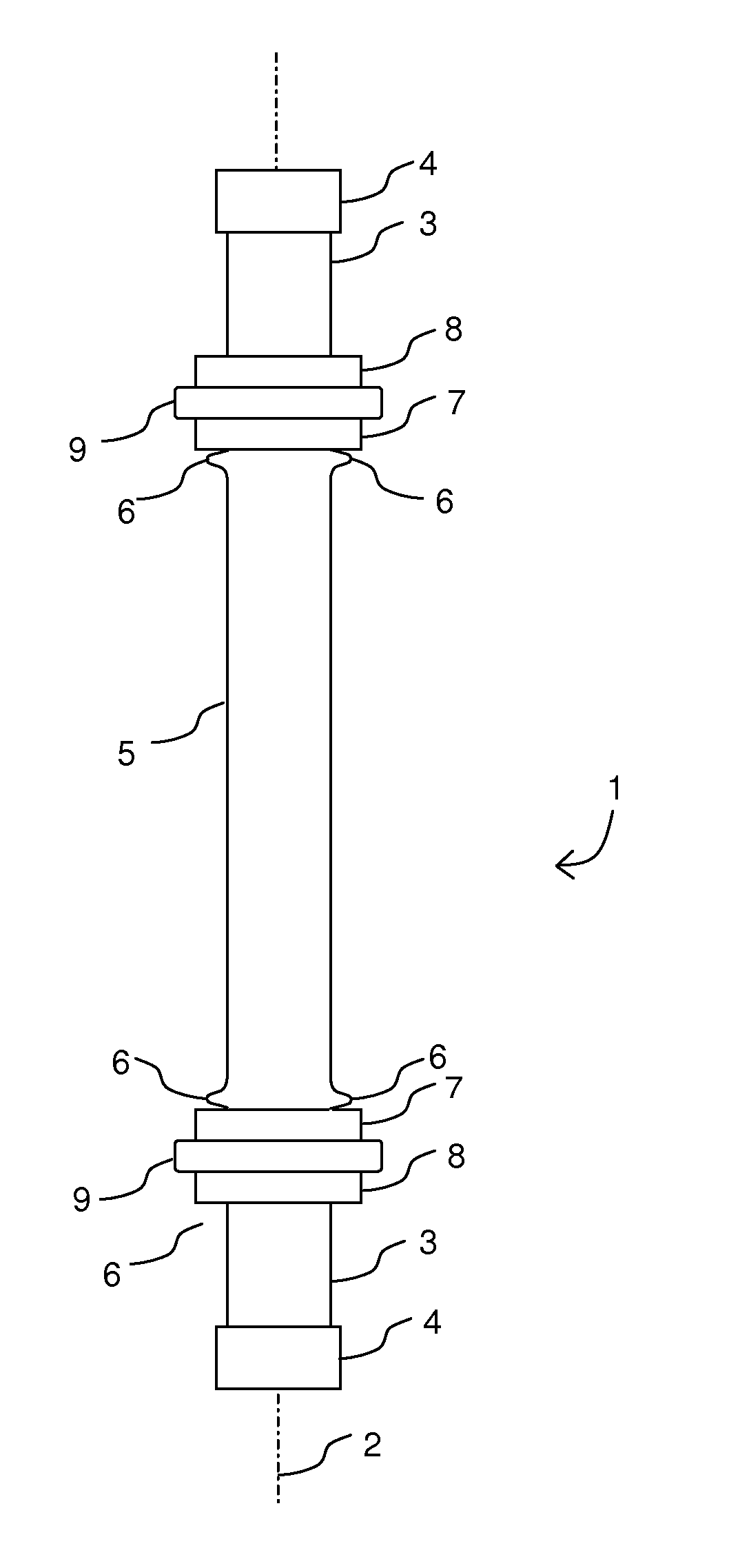
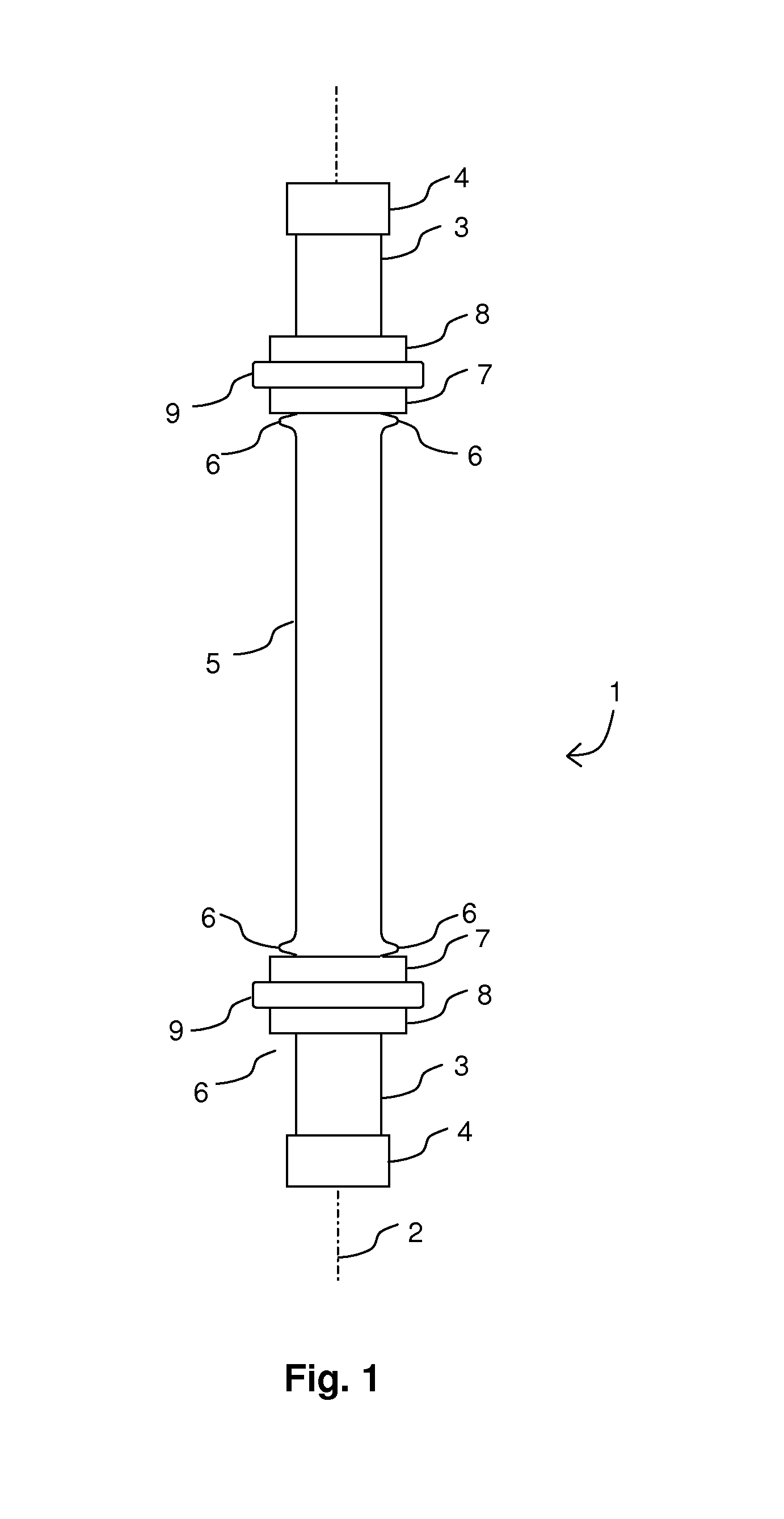
[0023]FIGS. 1 and 2 show a roll 1 of the present invention. The roll 1 includes a longitudinal axis 2 and opposite ends 3. End caps 4 cover each end 3. The body 5 of the roll 1 includes a cylinder comprising a substantially incompressible refractory ceramic, such as fused silica. The body 5 has an outer surface 22 and an inner surface 23. The inner surface 23 defines a cavity 24. The ends 3 may close the cavity 3 but, preferably, the cavity 24 remains open at either end 3. Open ends permits a metal rod 25 to extend through the cavity 24 between the end caps 4. Supports 26 hold the metal rod 25 along the longitudinal axis 2. An inner end plate 7 is adjacent to an inner retainer 6, in this embodiment, an abutment. The abutment 6 is present near each end 3. The inner e...


PUM

PropertyMeasurementUnit
densityaaaaaaaaaa
densityaaaaaaaaaa
densityaaaaaaaaaa

Abstract

The present invention describes a roll for use in glass manufacture, especially non-dusting TFT glass. The roll may include a hollow fused silica cylinder. End caps are mechanically fixed to the roll. Pulling flats are fixed in place by inner and outer end plates. A compression fitting secures at least the outer end plate to the roll. The roll may be reinforced with an internal metal rod that is secured to the shaft by a plurality of supports. The supports accommodate differences in thermal expansion.

Description

FIELD OF THE INVENTION[0001]The invention relates to a roll for use in the manufacture of glass and particular to pulling rolls for glass to be used in electronic applications.BACKGROUND OF THE INVENTION[0002]The production of glass sheet often requires rolls for pulling, supporting, and conveying the sheet at elevated temperatures. The glass will often have a temperature in excess of 500 C and frequently in excess of 650 C. Rolls must be capable of withstanding such operating temperatures for prolonged periods. Failure of the roll in a continuous production process can be very costly in time, man-power, material and lost revenue. The rolls should therefore resist thermally degradation, mechanically erosion, or dimensional changes, and should not negatively affect the glass.[0003]Rolls may support or convey a glass sheet through an annealing or heat treating furnace. Rolls may also flatten, lengthen or otherwise alter the dimensions of the glass. A roll may even generate a pulling f...

Claims


Application Information

Patent Timeline
Patent Type & Authority Applications(United States)
IPC IPC(8): C03B13/00
CPCC03B35/184C03B17/068C03B35/181C03B35/186C03B35/183
Inventor BUCKO, DWAYNENARDONE, JOSEPHSCHLACK, DOUGLASELLIOTT, RYAN
Owner VESUVIUS CRUCIBLE CO
Learn More