Focused ion beam apparatus

a technology focused beam, which is applied in the field of focused ion beam apparatus, can solve the problems of difficult to accurately grasp the crystal structure of the tip of the emitter, difficult to accurately grasp the crystal structure, and the crystal structure may become imperfect, so as to achieve clearer and high-luminance fim image, accurately grasped, and accurate determination

Active Publication Date: 2010-09-02
HITACHI HIGH TECH SCI CORP
View PDF2 Cites 31 Cited by
  • Summary
  • Abstract
  • Description
  • Claims
  • Application Information

AI Technical Summary

Benefits of technology

[0016]The invention was made in consideration of such circumstances, and the object of the invention is to provide a focused ion beam apparatus capable of accurately grasping the crystal structure of the emitter from a FIM image without being influenced by disturbances, such as contamination, and capable of accurately determining whether or not the crystal structure of the emitter has returned to the original state even if the rearrangement of atoms has been performed.

Problems solved by technology

However, it is difficult to accurately grasp the crystal structure of the tip of the emitter just by observing the FIM image.
Accordingly, just by observing the FIM image, it is difficult to distinguish between the emission resulting from the crystal structure of the tip of the emitter and the emission resulting from the contaminant and it is difficult to accurately grasp the crystal structure.
However, even if the rearrangement of atoms is arranged, there is a case where positive repeatability cannot necessarily be obtained each time and, depending on circumstances, the crystal structure may become imperfect.
However, it is difficult to determine even this just by seeing the FIM image.
However, since field evaporation is performed, the emitter is already brought into an unusable state when the confirmation of the crystal structure is ended.
Accordingly, as described above, just by seeing the FIM image, it is difficult to determine whether or not the crystal structure has returned to the original state, or is imperfect.
Similarly to the above-described contamination, this problem also leads to a decrease in the stability of the ion source.

Method used


Image

  • Focused ion beam apparatus
  • Focused ion beam apparatus
  • Focused ion beam apparatus

Examples


Embodiment Construction

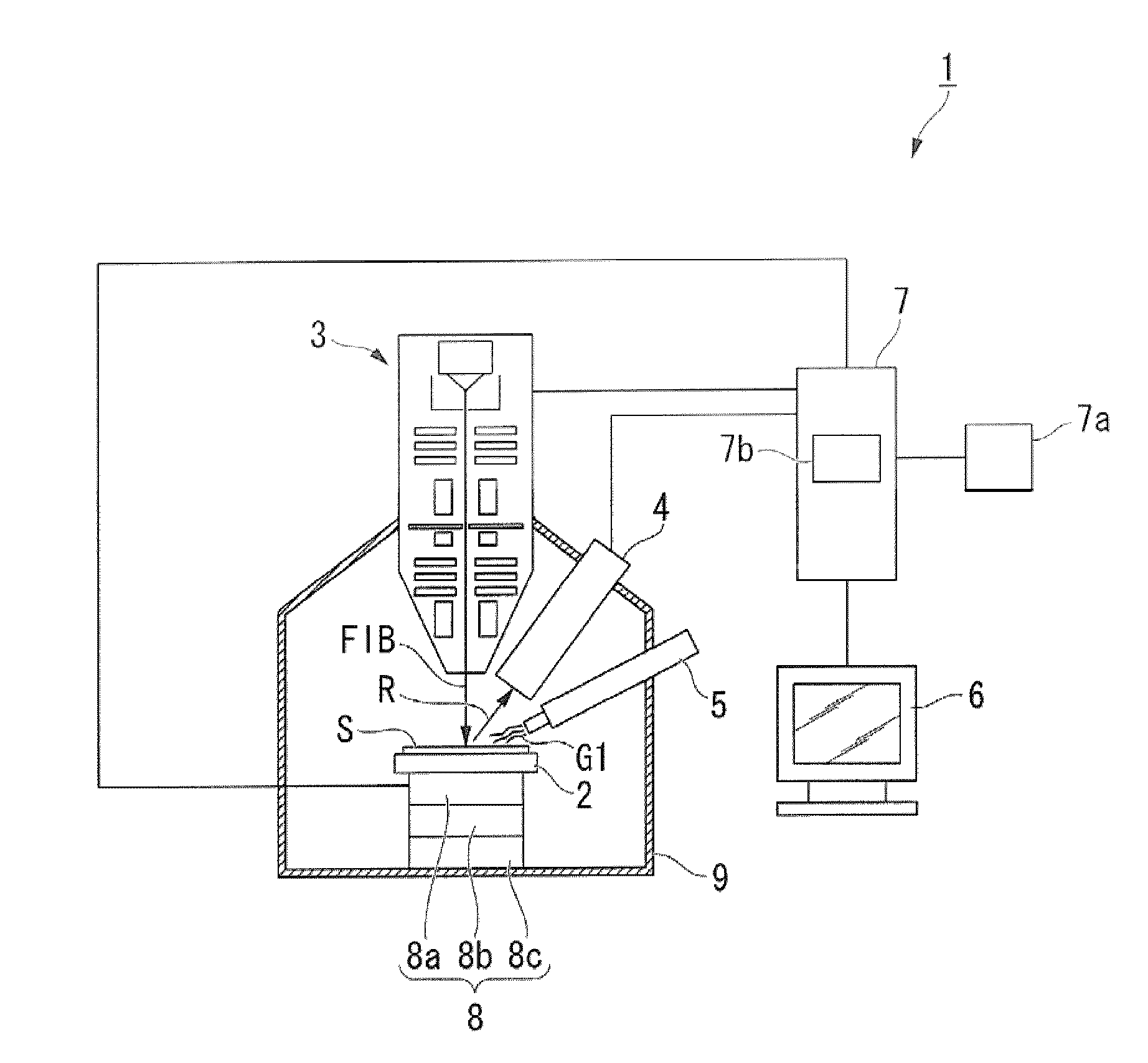
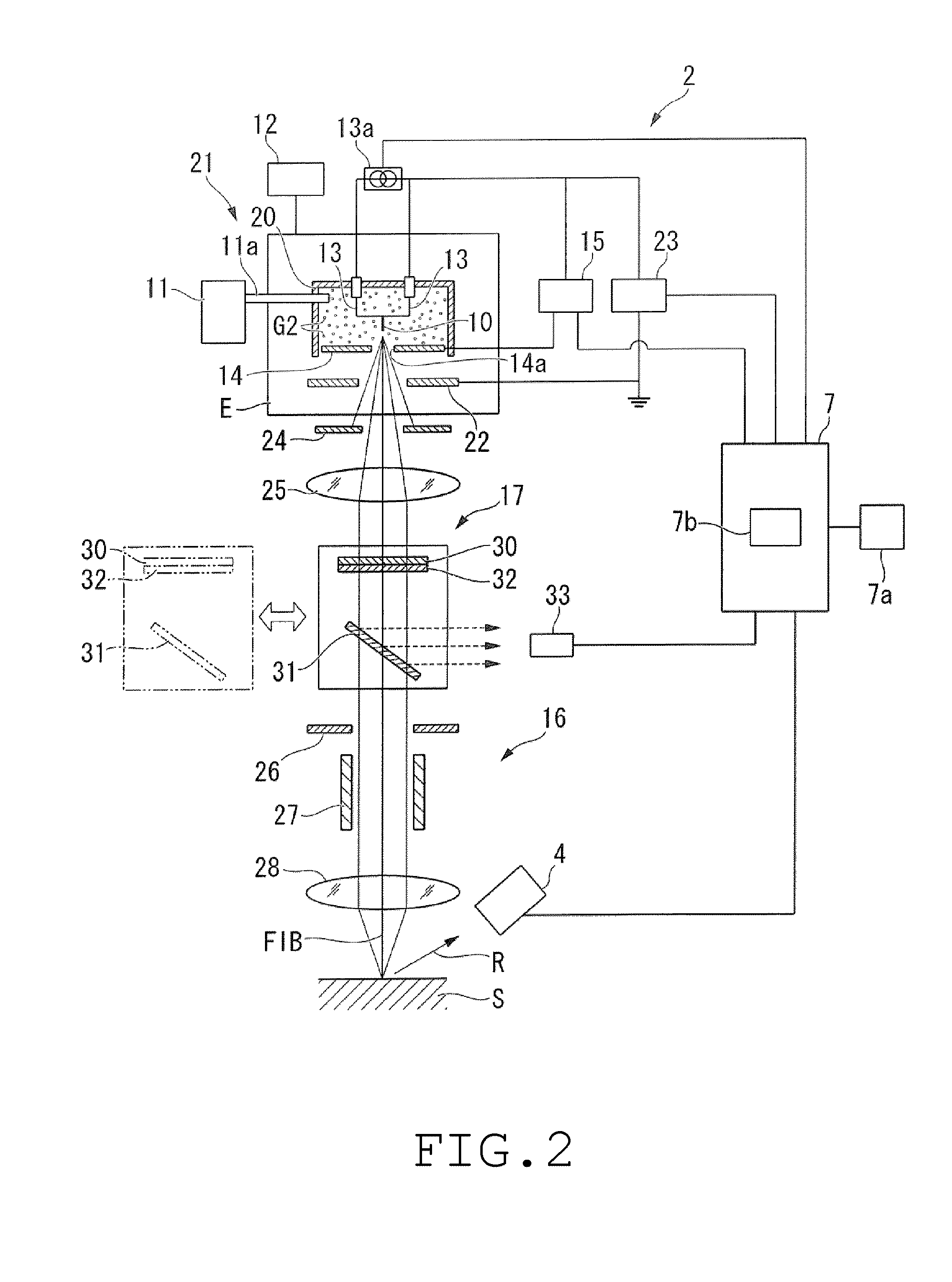
[0074]One embodiment according to the invention will be described below with reference to FIGS. 1 to 29. A focused ion beam apparatus 1 of this embodiment, as shown in FIG. 1, mainly includes a stage 2 on which a sample S is placed, a focused ion beam lens barrel 3 which radiates a focused ion beam (FIB), a detector 4 which detects secondary charged particles R generated by the radiation of the focused ion beam (FIB), a gas gun 5 which supplies a source gas G1 for forming a deposition film, and a control unit 7 which creates image data on the basis of the detected secondary charged particles R and displays the image data on a display unit 6.

[0075]The stage 2 is adapted to be actuated on the basis of an instruction of the control unit 7, and is adapted to be capable of being displaced in the directions of five axes. That is, the stage 2 is supported by a displacing mechanism 8 including a horizontal moving mechanism 8a which moves along an X axis and a Y axis which are parallel to a ...


PUM

PropertyMeasurementUnit
temperatureaaaaaaaaaa
extraction voltageaaaaaaaaaa
voltageaaaaaaaaaa

Abstract

The crystal structure of the emitter can be accurately grasped from a FIM image without being influenced by disturbances, such as contamination, and even if the rearrangement of atoms has been performed, whether or not the crystal structure of the emitter has returned to the original state can also be accurately determined. There is a provided a focused ion beam apparatus including an emitter 10, a gas source 11 which supplies gas G2, a cooling unit 12 which cools the emitter, a heating unit 13 which heats the tip of the emitter, an extraction power source unit 15 which applies an extraction voltage to ionize the gas into gas ions at the tip of the emitter, and then extract the gas ions, a beam optical system 16 which makes the extracted gas ions into a focused ion beam (FIB), and then radiates the focused ion beam onto a sample S, an image acquiring mechanism 17 which acquires a FIM image of the tip of the emitter, and a control unit 7 having a display unit and a storage unit 7b. A guide which displays an ideal crystal structure of the tip of the emitter is stored in advance in the storage unit. The control unit is enabled to display the guide in the state of overlapping the acquired FIM image on the display unit.

Description

RELATED APPLICATIONS[0001]This application claims priority under 35 U.S.C. §119 to Japanese Patent Application No. 2009-046366 filed on Feb. 27, 2009, the entire content of which is hereby incorporated by reference.FIELD OF THE INVENTION[0002]The present invention relates to a focused ion beam apparatus which has a gas field ion source.[0003]Conventionally, a focused ion beam apparatus is known as an apparatus for conducting observation various kinds of evaluation, analysis, etc. of samples, such as a semiconductor device, or taking out a fine flake sample from a sample and then, fixing this flake sample to a sample holder, to prepare a TEM sample.[0004]This focused ion beam apparatus includes an ion source which generates ions, and the ions which are generated in this ion source are radiated as a focused ion beam (FIB) afterward.DESCRIPTION OF RELATED ART[0005]There are several kinds of ion sources as the ion source. Although, for example, a plasma type ion source, a liquid metal i...

Claims


Application Information

Patent Timeline
Patent Type & Authority Applications(United States)
IPC IPC(8): G01N23/225H01J3/14
CPCH01J37/08H01J2237/31749H01J2237/0807H01J37/28
Inventor OGAWA, TAKASHINISHINAKA, KENICHIKOYAMA, YOSHIHIRO
Owner HITACHI HIGH TECH SCI CORP
Why Eureka
Try Eureka