
Solar energy system

a solar energy system and solar energy technology, applied in the field of solar energy, can solve the problems of waste of solar energy and under 18% efficiency of photovoltaic cells, and achieve the effects of convenient manufacturing, convenient price, and convenient configuration

Inactive Publication Date: 2010-09-09
FISCHER JAY D
View PDF16 Cites 28 Cited by
  • Summary
  • Abstract
  • Description
  • Claims
  • Application Information

AI Technical Summary

Benefits of technology

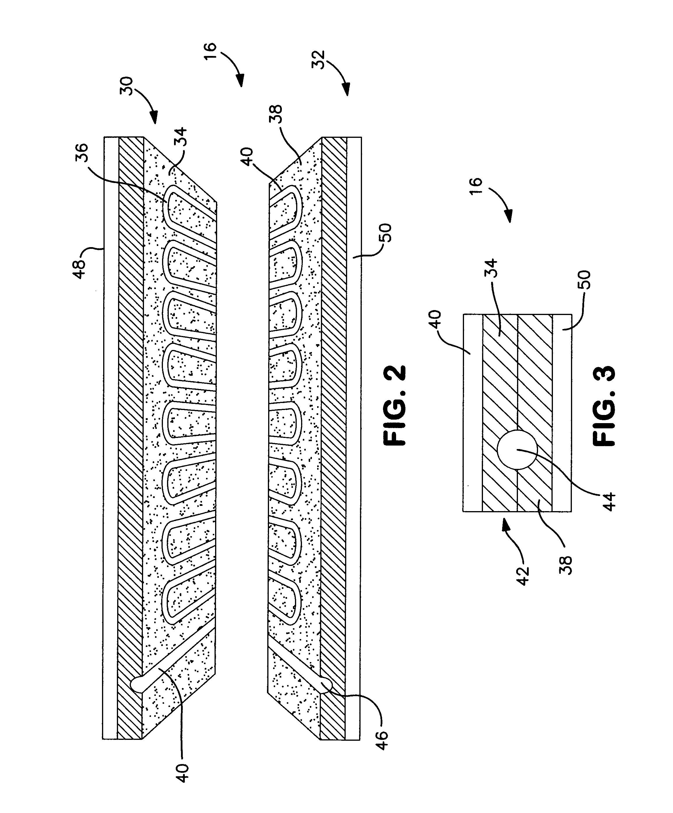
[0007]The present invention is a solar energy system, and one major innovation is the use of photovoltaic cells in conjunction with modular composite materials (thermally conductive compounds) forming hot water passageways to capture the traditionally wasted energy (heat) during co-generation of electricity. The solar panels heat the water using material passageways formed in the composite material in place of traditional copper or aluminum tubing. Another innovation is that the entire system is designed from inception as a fully modular product easy to manufacture, easy to configure, easy to price, easy to install and easy to maintain.
[0010]The advantages of the present invention include, without limitation, that smaller, modular solar panels can be produced in such a way as to be extremely efficient (more than anything on the market) through the use of embedded PV cells alongside the solar arrays to heat the water. Additionally, the use of the particular composite material for the water conduits is more economical, efficient, lighter and recyclable than existing copper or aluminum tubing.

Problems solved by technology

Typically, photovoltaic cells are under 18% efficient when generating electricity and therefore the rest of the solar energy is released (wasted) as heat.

Method used


Image

  • Solar energy system
  • Solar energy system
  • Solar energy system

Examples


Embodiment Construction

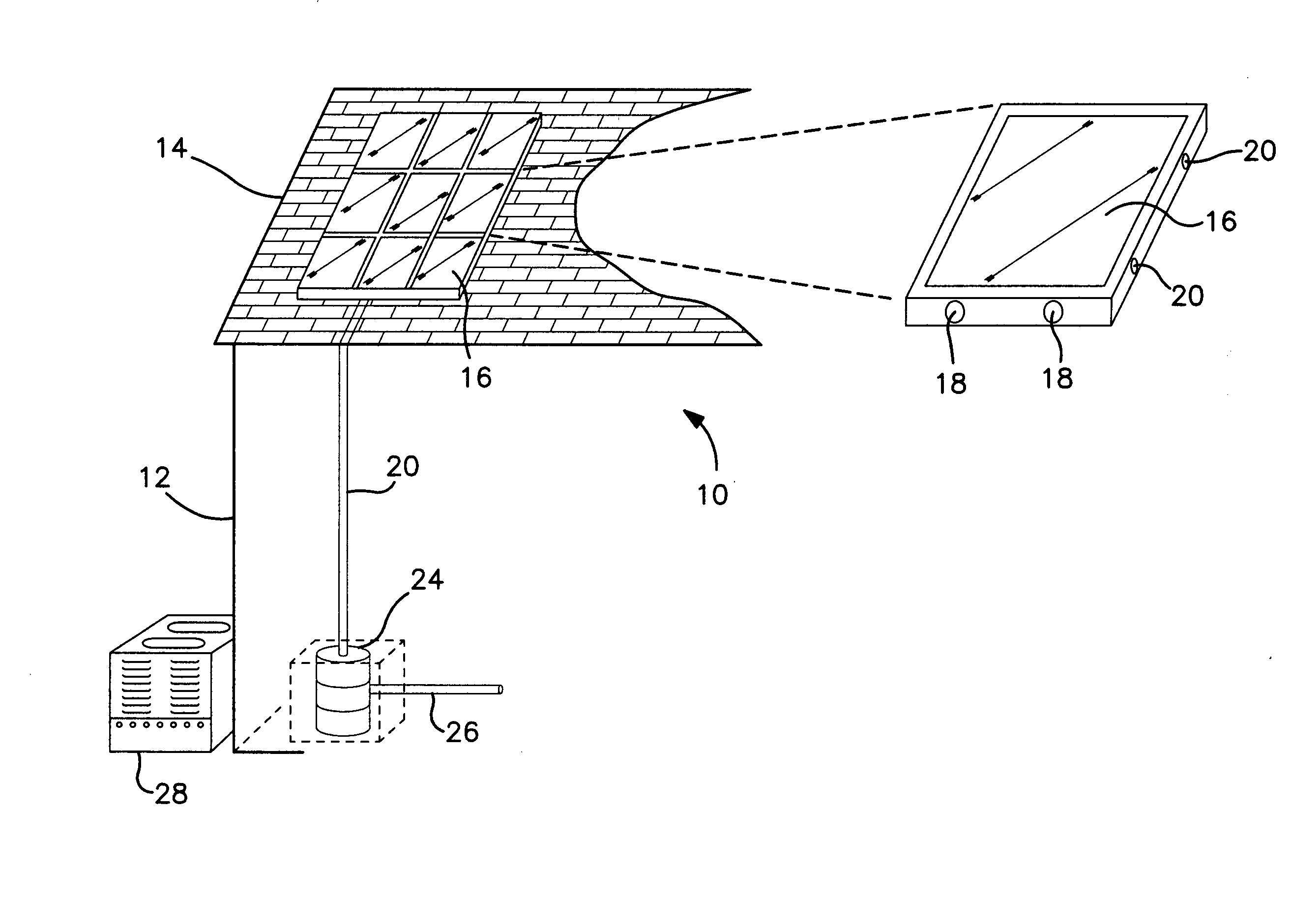
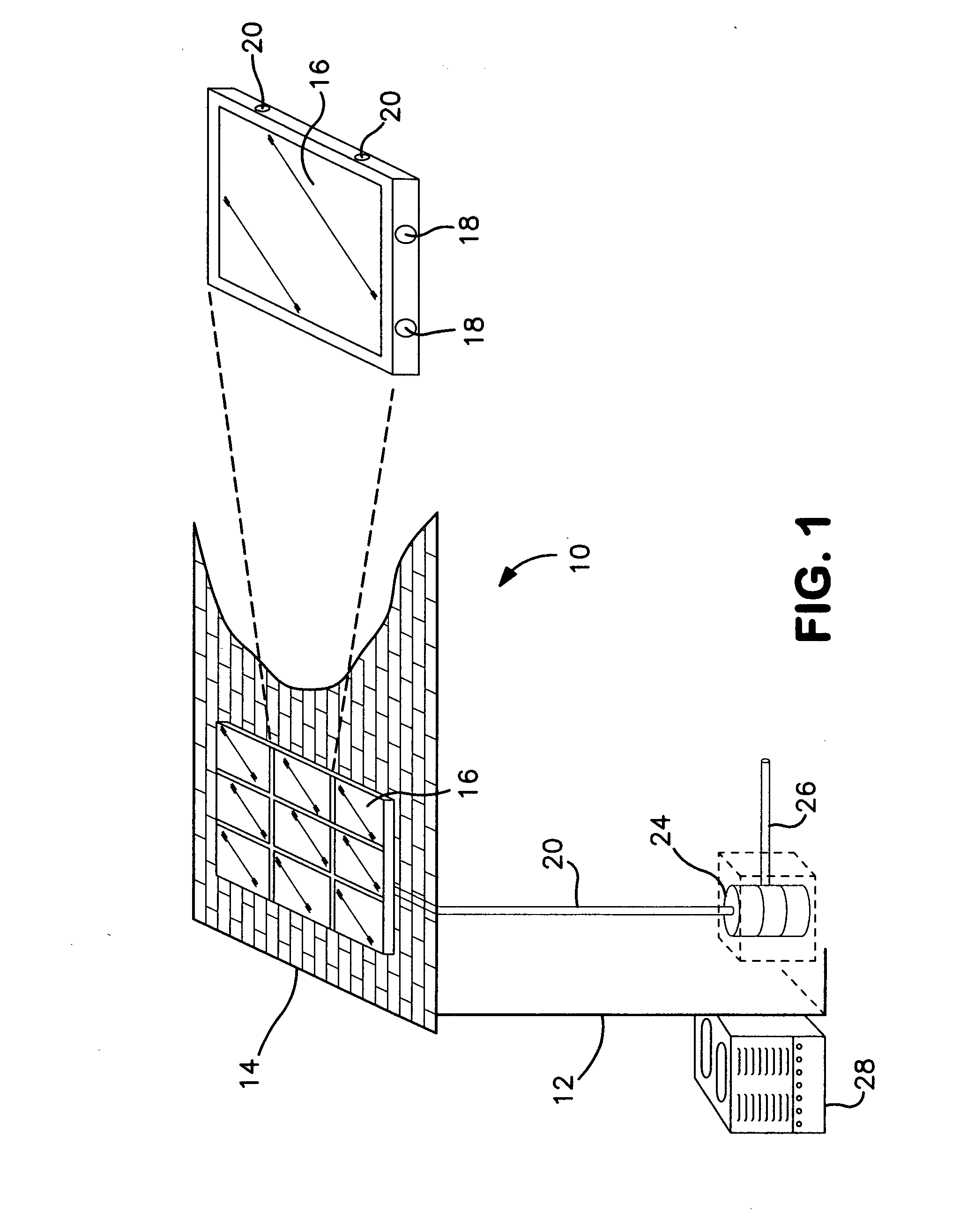
[0017]Turning first to FIG. 1, there is shown a schematic view, partially exploded, illustrating a solar energy system 10 constructed in accordance with the present invention. As can be seen, there is a building structure 12 with a roof 14 with an exposure to some form of sunlight, albeit direct or indirect. The building structure 12 can, of course, be any type of building that has a need for electricity and / or heated water. As will be seen, the present invention can be used with a structure that is devoted entirely to the production of heat, heated water and / or electricity and be a dedicated structure and not serve any other purpose such as for inhabitants.

[0018]As seen in FIG. 1, the roof 14 has a plurality of solar panels 16 arranged in columns (vertical alignment) and in rows (lateral alignment). As shown, there are nine (9) solar panels 16, however, as will become clear, the number of panels, their size and orientation may vary depending upon the particular installation, includ...


PUM

PropertyMeasurementUnit
thermal conductivityaaaaaaaaaa
heat conductivityaaaaaaaaaa
recessed areaaaaaaaaaaa

Abstract

A modular, solar energy system comprising one or more modular solar panels. The solar panels include a plurality of photovoltaic cells that are exposed to the radiant energy from the sun to create electrical power and are in heat transfer relationship with a water manifold through which water flows to remove heat from the PV cell as well as heat from the radiant energy. The heated water for the water manifold is used for heat / hot water and electricity system that can be configured using provided software and that can provide for any or all of the offerings (heat / hot water / electricity). The water manifold is constructed of a special high conductivity composite material that can be selected in accordance with the heat conductivity and customized for a particular installation. The system eliminates the use of copper and / or aluminum tubing, thereby reducing the cost and complexity of the system.

Description

CROSS-REFERENCE TO RELATED APPLICATIONS[0001]The present patent application is based upon and hereby claims priority to U.S. Provisional Patent Application, Ser. No. 61 / 209,007 filed Mar. 3, 2009 and the specification of that Provisional Application is hereby incorporated herein in its entirety by reference.BACKGROUND OF THE INVENTION[0002]The present invention is in the technical field of solar energy and, more particularly, the present invention is in the technical field of solar energy systems using solar panels for generating heat, hot water and / or electricity.[0003]There are, at the present, solar energy systems employing solar panels that gather the radiant energy from the sun to either heat water circulating therethrough, generate electricity or both. The current solar panels, however are not truly modular, and are not easily adaptable for differing conditions, heat output, prevalent weather conditions and the like. The conventional solar energy systems are not modular to the...

Claims


Application Information

Patent Timeline
Patent Type & Authority Applications(United States)
IPC IPC(8): H01L31/058F24J2/34B23P11/00
CPCF24D11/0221F28F3/12F28F21/065Y02B10/12Y10T29/49826Y02B10/70Y02B30/126Y02E10/60H02S40/44Y02B10/20Y02E10/50
Inventor FISCHER, JAY D.
Owner FISCHER JAY D
Learn More