Method of direct steam generation using an oxyfuel combustor

a technology of oxyfuel combustor and steam generation, which is applied in the direction of fluid removal, water heater, borehole/well accessories, etc., can solve the problems of low tolerance for other types of impurities, improper operation of the condenser of the power plant, etc., and achieve low or zero atmospheric emissions, and little or no atmospheric emissions

Active Publication Date: 2010-09-09
CLEAN ENERGY SYST
View PDF9 Cites 33 Cited by
  • Summary
  • Abstract
  • Description
  • Claims
  • Application Information

AI Technical Summary

Benefits of technology

[0019]Another object of the present invention is to provide a method for steam generation which produces exhaust gases rich in steam, which also contains combustion-derived carbon dioxide (CO2) with the CO2 optionally prevented from entering the atmosphere.
[0020]Another object of the present invention is to provide a method and system for removal of hydrocarbons from a hydrocarbon containing subterranean space which is enhanced by steam and CO2 injection into the subterranean space.
[0021]Another object of the present invention is to provide a method and system for removal of hydrocarbons from a subterranean space involving injection of steam into the subterranean space, with the steam generated in a manner which includes little or no atmospheric emissions.
[0022]Another object of the present invention is to provide a method and system for removal of hydrocarbons from a subterranean hydrocarb...

Problems solved by technology

Furthermore, some processes may have a high tolerance of some types of impurities and a low tolerance for other types of impurities.
For instance, any non-condensable gases within a...

Method used


Image

  • Method of direct steam generation using an oxyfuel combustor
  • Method of direct steam generation using an oxyfuel combustor
  • Method of direct steam generation using an oxyfuel combustor

Examples


Embodiment Construction

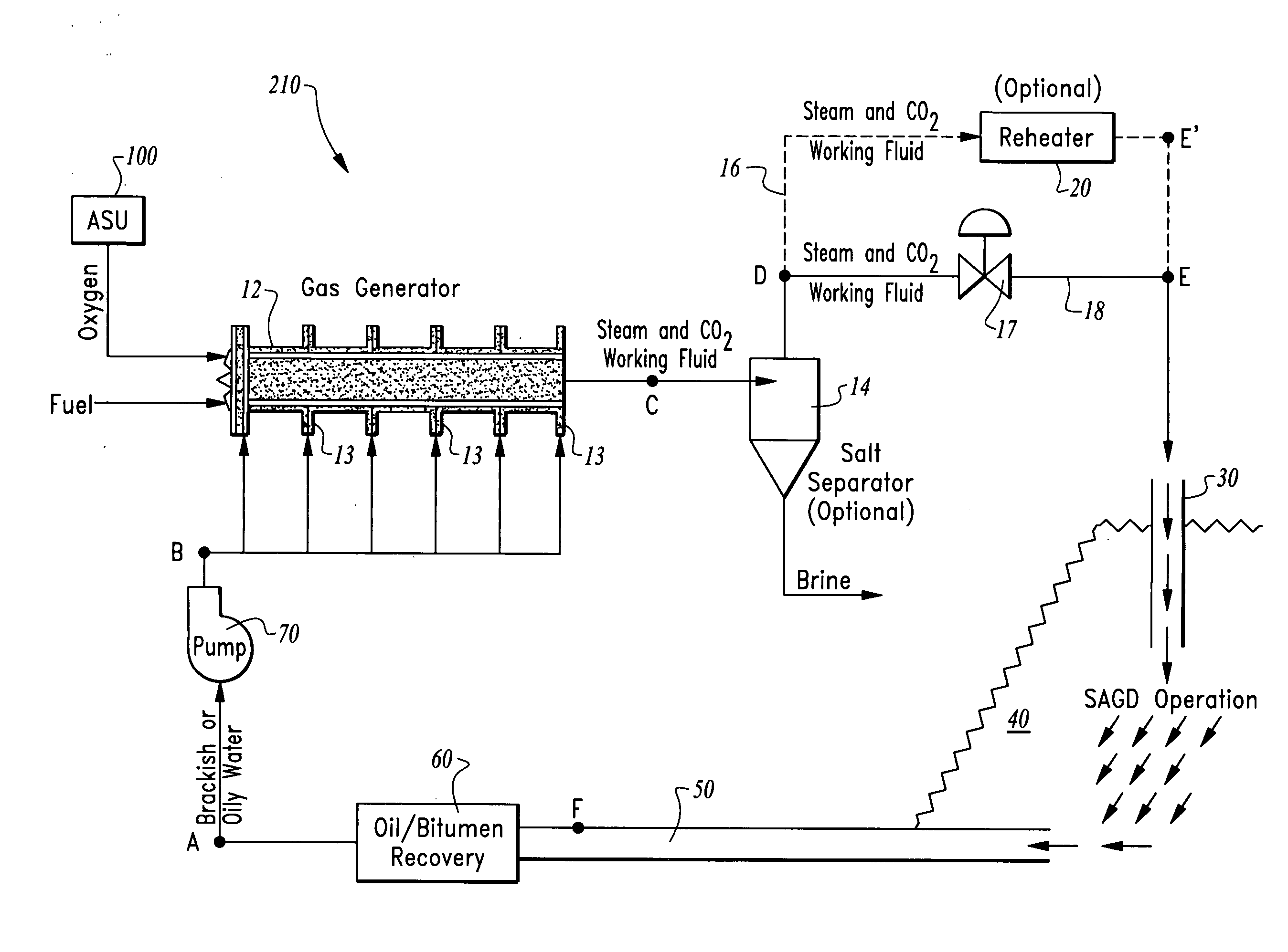
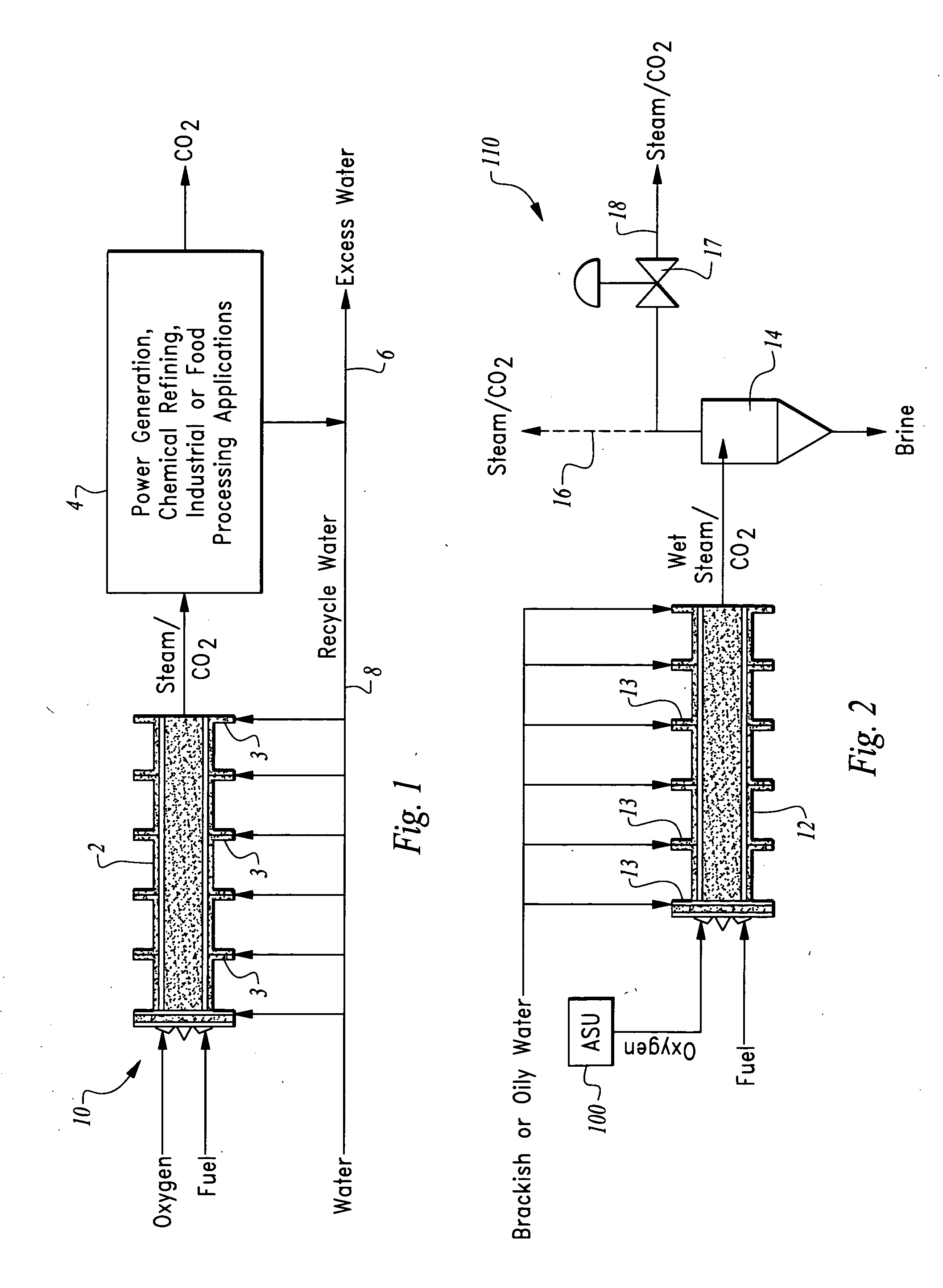
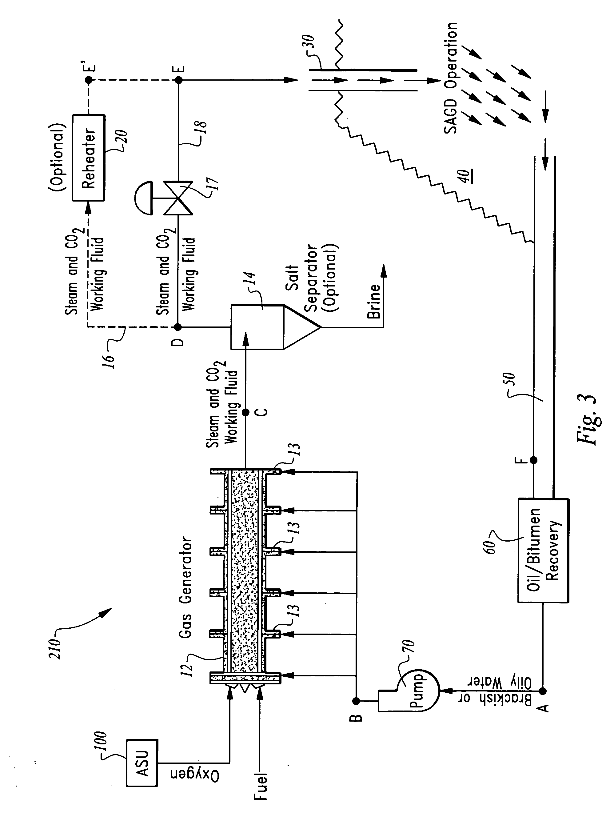
[0031]Referring to the drawings, wherein like reference numerals represent like parts throughout the various drawing figures, reference numerals 10, 110, 210 and 310 are directed to various systems and processes illustrative of embodiments of this invention. The systems 10, 110, 210, 310 each include a gas generator 2, 12 which is configured to combust an oxygen rich oxidizer with a hydrogen containing fuel, and with water inlets, resulting in the output of a high temperature steam and carbon dioxide mixture (or conceivably only steam if the fuel is carbon free). This steam and CO2 mixture can then be used for a variety of different processes (FIG. 1). If the water is “dirty” such as being brackish, a salt separator, such as a cyclone type separator 14 (FIGS. 2 and 3) can be utilized for separation of such contaminants before utilization of the steam / CO2 mixture. In the case of the water being oily, hydrocarbons within the water can potentially be combusted within the gas generator ...


PUM


Abstract

A gas generator is provided with a combustion chamber into which oxygen and a hydrogen containing fuel are directed for combustion therein. The gas generator also includes water inlets and an outlet for a steam and CO2 mixture generated within the gas generator. The steam and CO2 mixture can be used for various different processes, with some such processes resulting in recirculation of water from the processor back to the water inlets of the gas generator. In one process a hydrocarbon containing subterranean space is accessed by a well and the steam and CO2 mixture is directed into the well to enhance removability of hydrocarbons within the subterranean space. Fluids are then removed from the subterranean space include hydrocarbons and water, with a portion of the hydrocarbons then removed in a separator/recovery step. The resulting hydrocarbon removal system can operate with no polluting emissions and with no water requirements.

Description

CROSS-REFERENCE TO RELATED APPLICATIONS[0001]This application claims benefit under Title 35, United States Code §119(e) of U.S. Provisional Application No. 61 / 209,322 filed on Mar. 4, 2009.FIELD OF THE INVENTION[0002]The following invention relates to methods and systems for generating steam directly as products of combustion of oxygen with a hydrogen containing fuel. More particularly, this invention relates to methods of direct steam generation and utilization which generate both steam and carbon dioxide as products of combustion of a hydrogen and carbon containing fuel with oxygen and methods and systems for utilization of the resulting steam and carbon dioxide mixture in processes such as hydrocarbon recovery.BACKGROUND OF THE INVENTION[0003]Steam has many uses. For instance, steam is used in food processing, industrial processing, refining processes and chemical processes. Furthermore, steam can be utilized for power generation. Steam is also used to enhance oil and other hydro...

Claims


Application Information

Patent Timeline
IPC IPC(8): E21B43/24E21B43/34E21B43/22E21B43/40F24H1/00
CPCE21B43/2406F22B1/003F22B1/1853E21B43/34E21B43/24E21B43/2408E21B43/164
Inventor ANDERSON, ROGER E.PRONSKE, KEITH L.PROPP, MURRAY
Owner CLEAN ENERGY SYST
Why Eureka
Try Eureka